
Subscribe to Our Youtube Channel
Related Manuals for Lutron Electronics VISEO GRAFIK5000


Summary of Contents for Lutron Electronics VISEO GRAFIK5000
- Page 1 ™ ™ ® Viseo Display Control (VDC) Operation Manual ® LIGHTING CONTROL SYSTEM HELP & SCENES ZONES AREAS SYSTEM OMX-VDC-LB OMX-VDC-LF...
- Page 3 Notes...
-
Page 4: Table Of Contents
Table of Contents Step-by-Step Instructions Note: The letters VDC stand for Viseo Display Control. Viseo Display Control (VDC) Basics Page Basic Screen Layout ................................2 Location and Function of Buttons............................3 Fundamentals for Operating the VDC ..........................4 Normal Operation A. Monitoring the Scene Status in all Areas ........................5 B. - Page 5 Table of Contents Reference Sheets Page Troubleshooting Guide ............................26-27 Appendix A: Setting Up the Viseo Display Control (VDC) Setting the Address and Loading the Database Information into the VDC ..............28 Setting a New Access Code for the VDC ........................28 Setting the Default Area and Hidden Areas........................28 Setting the Contrast ..............................29 Appendix B: Including the VDC in the G5000/G6000 Database ................29 Appendix C: Saving Programming Changes Made at the VDC to the PC Database ........29-30...
-
Page 6: Viseo Display Control (Vdc) Basics
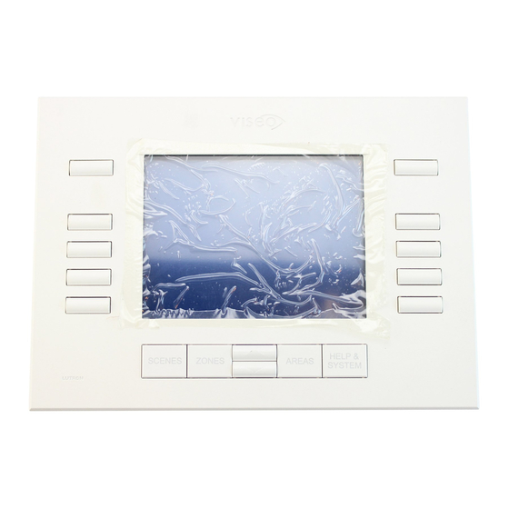
Viseo Display Control (VDC) Basics Basic Screen Layout Figure 1: Basic Screen Layout 1 Page title 2. Return to previous page (when active) 3. Current area being monitored, controlled, or programmed 4. Current scene of the current area 5. Scene number 6. -
Page 7: Location And Function Of Buttons
Viseo Display Control (VDC) Basics Location and Function of Buttons Direct Access Buttons Figure 2: VDC Button Layout 1. Previous Page (when available) - Displays the previous page of scenes, zones, or areas (i.e. lower numbered scenes, zones or areas). Note that this button also serves other purposes on some of the options pages. 2. -
Page 8: Fundamentals For Operating The Vdc
Viseo Display Control (VDC) Basics Before proceeding to the next section, Please read ! Fundamentals for Operating the VDC The letters VDC stand for Viseo Display Control. When viewing the Scenes, Zones, or Areas pages, the screen may not be able to display all of the scenes, zones, or areas that are in the system on a single page. -
Page 9: Normal Operation
Normal Operation Note: If the area/scene/zone that you want to monitor is not on the current page, use the PREVIOUS PAGE (top left -see page 3) and NEXT PAGE (top right - see page 3) buttons to navigate to other pages of areas/scenes/zones. A. -
Page 10: Selecting A Scene In An Area
Normal Operation D. Selecting a Scene in an Area 1. Press the AREAS button. 2. Select an area by pressing the button next to the appropriate area name. 3. Press the SCENES button. 4. Select a scene to activate by pressing the button next to the appropriate scene name. Current Area Selected... -
Page 11: Changing A Zone Level Manually
Normal Operation E. Changing a Zone Level Manually Note: All zone level changes discussed on this page are TEMPORARY and do not change the G5000/G6000 processor panel database settings. 1. Press the AREAS button. 2. Select an area by pressing the button next to the appropriate area name. 3. -
Page 12: Accessing The Help Screen
Normal Operation G. Accessing the Help Screen 1. If help with a page is necessary, press the HELP & SYSTEM button. 2. To exit help, press any of the direct access buttons or select EXIT HELP (bottom left button) to return to the previous page. -
Page 13: Programming Mode
Programming Mode Note: 1. The letters VDC stand for Viseo Display Control. 2. If the scene to be programmed is not on the current page, use the PREVIOUS PAGE (top left - see page 3) and NEXT PAGE (top right - see page 3) buttons to navigate to other pages of areas/scenes/zones. Programming mode allows the user to change the scenes saved in the G5000/G6000 database. -
Page 14: Online Programming Vs. Offline Programming
Programming Mode A. Entering Programming Mode (continued) Online Programming vs. Offline Programming There are two different programming modes in the GRAFIK 5000/GRAFIK 6000 system. In Online Programming, the light intensities in the selected scene of an area will change while programming the zone levels. During Offline Programming, the light intensities in the selected scene of an area will not change while programming the zone levels. -
Page 15: How To Program A Scene
Programming Mode B. How to Program a Scene Programming Zone Intensities of the Scene Note: If the current page is not the Zones: Setting Intensities page, select SET INTENSITY. 1. Select the zone(s) that needs to be changed. a. To deselect a zone, the button beside it MUST be pressed again. Simply pressing a different zone button will not deselect the previously selected zone. -
Page 16: Programming The Fade Rate Of The Scene
Programming Mode B. How to Program a Scene (continued) Programming the Fade Rate of the Scene 1. Select SET FADES, and the Zones: Setting Fades page will be displayed. 2. Select the zone(s) that that requires a fade rate change. a. -
Page 17: Programming The Delay Rate Of The Scene
Programming Mode B. How to Program a Scene (continued) Programming the Delay Rate of the Scene 1. Select SET DELAY and the Zones: Setting Delays page will be displayed. 2. Select the zone(s) that requires a delay rate change. a. To deselect a zone, the button beside it MUST be pressed again. Simply pressing a different zone button will not deselect the previously selected zone. -
Page 18: Selecting A Scene To Program
Programming Mode B. How to Program a Scene (continued) Selecting a Scene to Program 1. Press the SCENES button, and the Scenes: Select Scene to Program page will appear. 2. Select a scene to program, and the programming page for that scene will appear. Figure 12: Select Scene To Program Screen C. -
Page 19: Viseo Setup Menu
Viseo Setup Menu Note: The letters VDC stand for Viseo Display Control. A. Accessing the Viseo Setup Menu 1. Press HELP & SYSTEM. 2. Select VISEO SETUP MENU (bottom right button). 3. If required, enter the appropriate access code by selecting + (right side buttons) and – (left side buttons). Note: The default access code set at the factory is 1000. -
Page 20: Setup Menu Choices
Viseo Setup Menu B. Setup Menu Choices The Viseo Setup Menu allows the user to customize the VDC’s preferences. Use the side buttons to select these choices. Viseo Setup Menu Choices: 1. SET SYSTEM CLOCK - allows the user to set the date and time for the GRAFIK 5000/GRAFIK 6000 System. 2. -
Page 21: Set System Clock
Viseo Setup Menu 1. Set System Clock This page allows the user to set the date and time for the GRAFIK 5000/GRAFIK 6000 System. How to Set System Clock: a. Select each of the clock options (Hours, Minutes, Month, Date, and Year) and use the Raise and Lower buttons to change the entry to the desired value. -
Page 22: Unit Options
Viseo Setup Menu 2. Unit Options This page allows the user to adjust the following options: Link Address – sets the address of the VDC. This number is the same as the Wallstation link address number of the VDC in the database (see Appendix B: Including VDC in the G5000/G6000 Database). The address can be 1 through 32. -
Page 23: Area Setup
Viseo Setup Menu 3. Area Setup This page allows the user to change the settings for each of the areas. The possible settings are: Programmable – all users have access to program and select the scenes and switch the timeclock On and Off in this area. -
Page 24: Language
Viseo Setup Menu 4. Language These pages allow the user to change the display language for page titles, menu options, messages, etc. on the screen. The following languages are available: English Deutsche (German) Français (French) Nederlands (Dutch) Español (Spanish) Portuguêses (Portuguese) Italiano (Italian - on page 2) Note: This language option does not translate the area, scene, or zone names that are held in the database on the laptop. -
Page 25: Lcd (Liquid Crystal Display) Setup
Viseo Setup Menu 5. LCD (Liquid Crystal Display) Setup This page allows the user to change the LCD settings: LCD Contrast – change the contrast of the LCD. This value ranges from 0% (black) to 100% (white). LCD Backlight – change the intensity of the backlight of the LCD. This value ranges from 0% (off) to 100% (on full). Backlight Timeout –... -
Page 26: Access Code Menu
Viseo Setup Menu 6. Access Code Menu This page allows the user to make changes to the following access requirement settings: Access Code – enables (REQUIRED) and disables (NOT REQUIRED) the access code requirement. If the access code is required and a user tries to enter the Viseo Setup Menu, the user must enter an access code to continue. If the access code is not required, the user will not be prompted for an access code. - Page 27 Viseo Setup Menu 6. Access Code Menu (continued) How to Set a New Access Code: a. On the Access Code Menu page, select SET NEW ACCESS CODE. b. Enter the new access code by selecting + (right side buttons) and – (left side buttons). c.
-
Page 28: Read G5000/G6000 Data
Viseo Setup Menu 7. Read G5000/G6000 Data Selecting this option will download the area, scene, and zone names from the G5000/G6000 processor database into the VDC. This may take a few minutes, depending on the size of the database. This function also occurs automatically when the system is powered up. -
Page 29: Unlock/Lock Access
Viseo Setup Menu 8. Unlock/Lock Areas Pressing the bottom right button on the Viseo Setup Menu switches the unit between “Areas Unlocked” mode and “Areas Locked” mode. When this button displays UNLOCK AREAS, the VDC is in "Areas Locked" mode. “Areas Locked”... - Page 30 Troubleshooting Guide Note: The letters VDC stand for Viseo Display Control. Troubleshooting Guide Symptoms Possible Causes and Remedies Is the VDC powered? Check for 12-35V from terminals 2 to 1 on the Wallstation Screen is blank and the backlight is not On. link.
- Page 31 Troubleshooting Guide Troubleshooting Guide (continued) Symptoms Possible Causes and Remedies The VDC keeps resetting Check the wiring - are there any bad connections? without anyone touching the Is there another Control addressed the same as the VDC? control. Make sure that there is a link termination at both ends of the Wallstation Link. Is the appropriate operating code loaded into the G5000/G6000 processor? Make sure that there is a link termination at both ends of the Wallstation Link.
- Page 32 Appendix A Appendix A: Setting Up the Viseo Display Control (VDC) Setting the Address and Loading the Database Information into the VDC If the VDC is addressed correctly when it is powered up and connected to the Wallstation link, the unit will begin downloading the database information.
- Page 33 Appendices A, B, & C Appendix A: Setting Up the Viseo Display Control (VDC) (continued) Setting the Contrast 1. Press HELP & SYSTEM. 2. Select VISEO SETUP MENU. 3. If needed, enter the access code by selecting + and –. 4.
- Page 34 Appendices C & D Appendix C (continued) 8. Click on OK, if necessary. 9. Click on DONE. 10. Another message will appear that reads, “WARNING! There Are Scenes In The System Which Have Been Modified In The GRAFIK 5000/GRAFIK 6000. This Means The Current Data File May Not Match The Date In The GRAFIK 5000/GRAFIK 6000.
- Page 35 Appendix E Appendix E: VDC Wallstation Link Requirements Note: The VDC draws more current than a standard Wallstation. G5000/G6000 Wallstation Link Controls: # Wallstations/VDCs # Power Units Wallstation Link Max 32 - 128* Standard Wallstation Viseo Wallstation Note: Adding a MUX-Repeater (MUX-RPTR) increases the # of power units by 32. * Each VDC requires 4 power units with a maximum of 32 Wallstations (4 x 32 = 128).
- Page 36 Lutron GL (Singapore) Lutron, GRAFIK Eye, GRAFIK 6000, and the Sunburst design are registered International ++49-30-97-10-4590 Tel: ++65-220-4666 trademarks; GRAFIK 5000 is a trademark of Lutron Electronics Co., Inc. Fax: (309) 710-4591; Fax: ++65-220-4333 © 2002 Lutron Electronics Co., Inc.
Need help?
Do you have a question about the VISEO GRAFIK5000 and is the answer not in the manual?
Questions and answers