
Related Manuals for KeLi XK3101

Summary of Contents for KeLi XK3101
- Page 1 XK3101 (KM05 ) Weighing Transducer User Manual Read the manual carefully before use Please take good care of this manual for future reference www.kelichina.com Page 1 of 17...
- Page 2 1. General Description KM05 is a weighing transducer promoted by Keli Electric Manufacturing (Ningbo) Co., Ltd. It applies for an industrial control fields (or other applications with analog output). It combines weight display and analog signal together. Its signal transaction of former part adopts high-precise A/D converter with 24 bits, and the output of analog signal adopts D/A converter with 16 bits.
- Page 3 Zero temperature drift: 0.06 uV/℃ Max. Sensitivity: 0.6uV/d Non-Linearity: ≤0.01%FS Drift of analog output (0mA or 4mA): 50PPM/℃ Output drift (20mA or 24mA): 50PPM/℃ c. Power supply Voltage range of weighing transducer is AC 187 ~ 242V, frequency is 49~51Hz, maximum power consumption is 6 watt.
- Page 4 Fig. 8.4-2 Before installation, mandril of both sides of weighing transducer should be removed firstly, and then weighing terminal is put into the cabinet. The two mandrils are fixed to both sides of weighing terminal tightly to guarantee the firm installation of weighing transducer.
- Page 5 c. Connection of load cell and weighing transducer Load cell adopts 9 wire plugs; end of weighing transducer is a hole. Definition for foot signal takes fig. 8.4-3 for reference. Fig. 8.4-3 If four wire shield cable is use, Exc + and Sen+, Exc- and Sen- must be connected, Connection for load cell to indicator and shield cable to ground must be reliable.
- Page 6 e. Analog output connection (Fig. 8.4-5) Transducer can choose voltage and current output. Connecting wire uses in-out connection end. The middle part is the common part for analog signals. Output of voltage and current are connected to different ends. To the backboard, the right one is current output, middle one is the common part and the left one is voltage output.
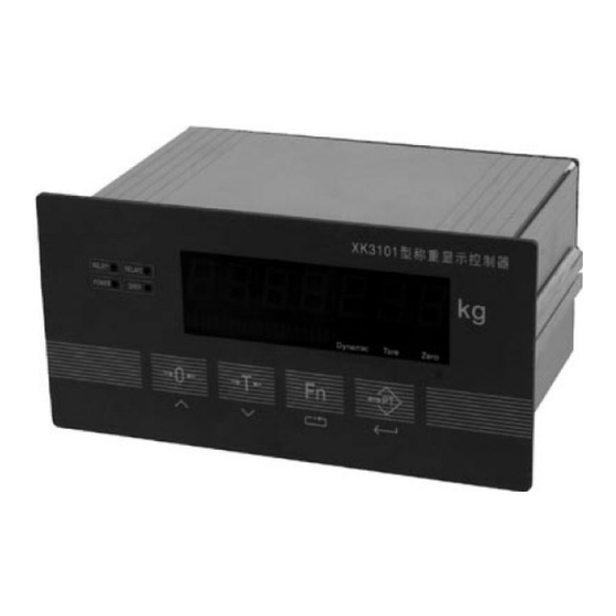
- Page 7 3. Display Panel (Fig. 8.4-7) XK3101 (KM05) weighing transducer has four buttons on display Panel, used for all operations and parameters set-up for indicator. Zero button, it is value increased button when in set-up state Tare button, return (or value decreased) button, when in set-up state.
- Page 8 then the highest bit transmits “-“ For example: Indicator displays “12345”, serial port transmits data “=0012345” Indicator displays “1234.5”, serial port transmits data “=012345” Indicator displays “-12345”, serial port transmits data “=-12345” Data frame keeps 7 bits all the time, including radix point 5.
- Page 9 c. Press [ PT ] button, indicator displays “ ”, press [ Fn ] button to choose divisional value. d. Press [ PT ] button, indicator displays “ ”, then press [ Fn ] button to choose parameters. When F1.1=0, it means normal calibration of two points (zero point and another weighing point).
- Page 10 Note: when uV of each division is less than 0.6 uV, indicator will show “E4”, then press [ Tare ] button, it returns to the previous step. Press [ PT ] button, the calibrated result can be accepted. In other words, uV of each division is less than 0.6nV, indicator still work correctly.
- Page 11 Analog output can choose one of the following modes: 0-20mA、4-20mA、0-5V and 0-10V. Choose according to the following steps: Press [Fn] and [ 0] buttons simultaneously, indicator displays “ ” Press [Fn] button for three times continuously, indicator displays “ ” Press [ PT ] button, indicator displays “...
- Page 12 output will work according to chosen weight transducing range. 6.3. Adjust bottom and top of analog output Calibrating four analog outputs before delivery, thus choosing mode of analog output is enough when using it. Bottom and top of analog output can be changed if necessary, for example, you can set analog output range from 1V to 4.5V.
- Page 13 select parameter by pressing [Fn] button. Press [PT] button to next parameter choice. d. Press [Tare] button for many times at any time, Press [PT] button to quit out when indicator displays “ESC” 7.2. Content of function F2 choice parameter F2.1 to choose ADC transmitting speed rate 0=7.5Hz;1=15Hz;2=30Hz;3=60Hz (available when turn it on next time) F2.2 to tare...
- Page 14 Weight separate selective mode: 1#relay: weight ≤out 1 value, close weight >out 1 value, cut 2#relay: weight <out 2 value, cut weight ≥out 2 value, close Fixed value mode: 1#relay: weight ≤out 1 value, cut weight >out 1 value, close 2#relay: weight <out 2 value, cut weight ≥out 2 value, close 8.1.
- Page 15 Press [Tare] button for many times, and press [PT] button to quit out when indicator displays “ Please contact KELI if you want to get the protocol of multi-indicator’s communication. KELI also can make custom-built protocol per customer’s request.
- Page 16 11. Prompt examinations for some parameters Press [Fn] button to examine some parameters in normal working. Every time press it, contents of one item will be displayed. If it keeps on some contents more than 6 seconds, it will return to normal working state automatically. Content “1PXXXXX”...
- Page 17 Phenomenon 4: No analog output Solution: 1. Check mode of analog output if it is correct 2. Check wire connection of analog output end if it is correct 3. Turn to set-up choice 6.3 adjustment of bottom and top of analog output, to check if corresponding analog value of analog output bottom and top is correct Phenomenon 5: No data of serial interface...
Need help?
Do you have a question about the XK3101 and is the answer not in the manual?
Questions and answers