
Related Manuals for KeLi XK3101+

Summary of Contents for KeLi XK3101+
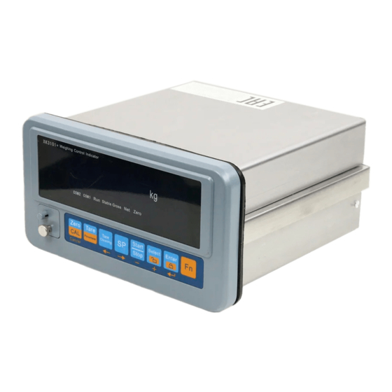
- Page 1 XK3101+ Weighing Transducer User Manual March 2009 version Keli Electric Manufacturing (Ningbo) Co.,Ltd.
-
Page 2: Table Of Contents
Index 1 PRODUCT STRUCTURE ......................1 1.1 G ......................1 ENERAL DESCRIPTION 1.2 D ....................1 IMENSION AND NSTALLATION 2 MAIN SPECIFICATION ......................1 3 TECHNICAL SPECIFICATION ....................2 3.1 A ..........................2 NALOG PART 3.2 O ......................2 UTER INPUT AND OUTPUT 3.3 S ..................2 ERIAL OMMUNICATION NTERFACE 3.4 PROFIBUS I... - Page 3 APPENDIX C MODBUS COMPATIBLE COMMUNICATION MODE .......34 APPENDIX D PROFIBUS-DP INTERFACE (OPTIONAL)............36 APPENDIX E CALIBRATION PARAMETERS RECORD LIST ..........37 APPENDIX F DEFAULT PARAMETER BEFORE LEAVING FACTORY......38 SHIPPING LIST OF XK3101+WEIGHING INDICATOR ............39...
-
Page 4: Product Structure
1 Product Structure 1.1 General description XK3101+ is a weighing transducer applies for industrial control fields, which has several serial communication interfaces such as Modbus and Profibus, interfaces for switching value input and output and extendible analog. Switching value output can deploy four methods that can be used in some applications such as batching, feeding fixed value, upper and lower limits checking and so on. -
Page 5: Technical Specification
※ Standard RS232/RS485 communication interface isolation ※ Standard 10-way (optical coupling isolation)switching value (4-way input 6-way OC output) ※ Locking keyboard ※ Extendible Profibus interface (optional) ※ Extendible interface for 4-20mA/0-10V analog output (optional, accuracy:0.2%) ※ Built-in assisted DC12V/300mA power output( can drive relay output) ※... -
Page 6: Analog Output Module (Optional)
Max transmission speed of bus :12M bit/s, baud rate adapting. Support synchronization and frozen modes. 3.5 Analog output module (optional) Analog output module includes 0-10V voltage output and 4-20mA current output, but they can not be used at same time. Voltage output requires loading resistance not less than 100 kΩ, current output requires loading resistance not more than 500Ω. -
Page 7: Keys
COM1 Communicating indication of serial communication interface 1 (MODBUS compatible mode, continuous sending mode 1/2) ; COM2 Communicating indication of serial communication interface 2 (Profibus interface) Low-order This cursor is lighting means the key was locked, buzzer will bits ‘12’ continuously call three times when you press any key before unlocking the key 4.2 Keys... -
Page 8: Basic Operation
4.3 Basic operation 4.3.1 Power on Indicator will do a series of self-checking when it is power on, if everything is normal, it will return to normal displaying state. During the process of self-checking, indicator will show communication baud rate, communication bus, analog output type and other information. -
Page 9: Installation And Debugging
You can not lock the key while setting the parameters or batching. 4.3.6 Unlock the key Press key ‘ Fn’ and key ‘Select’ at same time, digits 1 and 2 appear in the first figure on the right side of indicator, which means the key is unlocked. 5 Installation and Debugging 5.1 Electric connection 5.1.1 Sketch for terminals on back side... - Page 10 6-core signal wire was recommended, the length of signal wire from indicator to junction box will not over 50M. 5.1.3 Serial interface Serial interface of indicator include RS232 and RS485. Pins assignment are as follow: Mark Signal RS485 A port RS485 B port Grounding RS232 data send...
- Page 11 effective, duration of signal short-circuit is at least 50MS. Switch, relay or transistor can be used in outer input circuit. Input current is about 3mA, leakage current of input device can not over 100 microampere. The distance of connecting pins between input interface and outer equipment can not over 10M, we do not suggest to near AC power line and power line.
- Page 12 +12V Controlling point INPUTx Input is effective when the controlling port is logic 1 5.1.4 .2 output output circuit of indicator adapts transistor OC type, the transistor turns on when output is effective,, max absorbed current of the output circuit is 50mA , outer driving voltage can not be over DC30V, equivalent circuit of each output is as follows: +12V OUTX...
-
Page 13: Current Output
5.1.5 Expansion of analog output There are two kinds of analog output as 4~20mA and DC0~10V. Both they are can be calibrated separately, but can not be used together, you can select one type by setting parameters. The max loading resistance is 500Ωwhen the output is 4~20mA, DC 0~10V output requires minimum loading resistance is 100 kΩ.The connector for analog output is 3-pin terminal as follows: mark... -
Page 14: Scale Calibration
5.2 Scale calibration New installed or maintained scale shall be calibrated before using, indicator has three kinds of calibration procedures, they are weight ( or alternate) calibration、 replace calibrated parameters and input scale parameters three methods. Weight (or alternate) calibration is recommended for new installed scales, if loading weight (or alternate) on spot is not convenient, can use the other two calibration methods, but please note, their calibration error usually is bigger than weight (or alternate) calibration. -
Page 15: Calibration Procedure 0: Weight Calibration( Or Alternate)
5.3 calibration procedure 0: weight calibration( or alternate) Press Enter to confirm (weight calibration procedure ) Press Zero to exit Press SP button to move right one digit Press Tare Cleaning button to move left one digit PC. 0000 Press Select button to increase one on data Input password 2008 Press Start/Stop button to reduce one from data Press Enter button to confirm... - Page 16 Press SP button to move right one digit 0000.000 Press Tare Cleaning button to move left one digit Input weight value of the weight Press Select button to increase one on data Press Start/Stop button to reduce one from data Press Enter button to confirm Error prompt E--7 Input value=0 or...
-
Page 17: Calibration Procedure 1:Replace Calibrated Parameter
5.4 Calibration procedure 1:replace calibrated parameter Press Enter to confirm (replace calibrated parameter) Press Zero to exit Press SP button to move right one digit Press Tare Cleaning button to move left one digit PC. 0000 Press Select button to increase one on data Input password 2008 Press Start/Stop button to reduce one from data Press Enter button to confirm... - Page 18 Press SP button to move right one digit Press Tare Cleaning button to move left one digit PARA3 0.xxxxxx Press Select button to increase one on data Input parameter 3 Press Start/Stop button to reduce one from data Press Enter button to confirm Press SP button to move right one digit PARA4 xxxxxx Press Tare Cleaning button to move left one digit...
-
Page 19: Calibration Procedure 2: Input Scale Parameter
5.5 calibration procedure 2: input scale parameter Press Enter to confirm (input scale parameter) Press Zero to exit Press SP button to move right one digit Press Tare Cleaning button to move left one digit PC. 0000 Press Select button to increase one on data Input password 2008 Press Start/Stop button to reduce one from data Press Enter button to confirm... -
Page 20: Special Explanation For Calibration Procedure
5.6 Special explanation for calibration procedure If separately calibrate zero point, may select weight calibration procedure, when display Add Ld1, press Zero button to exit. If use input scale parameter calibration procedure to calibrate, scale self-weight can be to clear by separately calibrating zero point; or use input calibrated parameter procedure to modify PARA5, modify zero point by manual. -
Page 21: Using Environment Parameter(Group2
parameter)、GROUP3(serial communication parameter)、GROUP4(on-off output parameter)、GROUP5(analogy output parameter) The functions of related button when setting parameters are shown as following: Zero: exit button, back to upper parameter setting; Tare Cleaning: move left button, move modified data to left on digit; SP: move right button, move modified data to right one digit; Select: select parameter list, increase one on data when inputting data;... -
Page 22: Serial Communication Parameter(Group3
x=0 dynamic checking is forbidden x=1 allow, the sensitivity of dynamic checking is 0.5d x=2 allow, the sensitivity of dynamic checking is 1d x=3 allow, the sensitivity of dynamic checking is 3d 26 digital filter option x=0~7; the number stands for filter intensity, the bigger the value is , the stronger the filtering ability is , so related stable time also become longer. -
Page 23: Profibus-Dp Interface
select the complement of the sum data, that is calibration sum character. 35 output mode x] output mode x = 0 modbus compatible mode ( see appendix C: modbus compatible communication mode) x = 1 continuous output mode 1 ( see appendix A: continuous output mode1) x = 2 continuous output mode 2 ( see appendix B: continuous output mode... - Page 24 6.3.1 Each pattern state on-off output corresponding: a. Two material dual-rate feeding X=0 During matching state, indicator display N.W of feeding material. Press “Start/Stop” button or “INPUT1” to pause present matching process, repress “Start/Stop” button to run new matching process. Note 1: Material over status dealing, “OUT5”...
- Page 25 b. Four materials single speed feeding X=1: During matching state, indicator display N.W of feeding material, Press “Start/Stop” button or “INPUT1” to pause present matching process, repress “Start/Stop” button to run new matching process. Note 1: material over status dealing “OUT5” will output (as up diagram indicate), screen glittering display simultaneity the different value, press “Enter”...
- Page 26 c. Fixed value pattern X=2 Fixed value pattern “OUT5” and “OUT6” is not open. d. Up/down limit pattern X=3: Up/Down limit pattern, “OUT5” and “OUT6” is not open. - 23 -...
- Page 27 6.3.2 “Preset Point” setting instruction Each output pattern, the setting of Preset Point is different. Beneath display the details of setting flow. a. Two materials and two speed feeding X=0: Dead matching status, press “SP” button. Press “SP” button to move to right 1 digit Press “Tare Cleaning”...
- Page 28 Indicator display “dr2”, then display set Press “SP” button to move to right 1 digit value. Press “Tare Cleaning” button to move to left 1 digit. dr2: material 2 slow feeding value. Press “Select” button to add number 1 Press “ON/OFF” button to minus number 1 Press “Fn”...
- Page 29 b. Four material single speed feeding X=1 Press “SP” button to move to right 1 digit Dead matching status, press “SP” button. Press “Tare Cleaning” button to move to left 1 digit. Press “Select” button to add number 1 Press ON/OFF button to minus number 1 Indicator display “SP1”, then display set Press “Fn”...
- Page 30 c. Fixed value pattern X=2 Dead matching status, press “SP” Press “SP” button to move to right 1 digit Press “Tare Cleaning” button to move to left 1 digit. Indicator display “SP1”, then display set value. Press “Select” button to add number 1 SP1: fixed value point 1.
-
Page 31: Simulation Value Output Parameter (Group5)
6.4 Simulation value output parameter (GROUP5) [GROUP 5] [5.1 x] Simulation value output optional unit configure. No simulation value output optional unit. x=4-20 Circuit output 0-20mA. x=0-10 (DC0~10V) ; [5.2 x] Simulation value output optional x=0 Simulation value output optional corresponding G.W. x=1 Simulation value output optional corresponding N.W. -
Page 32: Malfunction Information And Settlement
7 Malfunction information and settlement 7.1 Error indicator symbol Item Display Possible reason Solution E - - 1 Calibration code error Wrong operation as: E - - 2 Forbidden clear zero dynamic tare function or tare function forbidden status to press TARE button. -
Page 33: Daily Cleaning And Maintenance
b. Serious electromagnetism interfere around, or hi-power frequency conversion equipment influence. (2) The weighing result is twinkling in a range. Possible reason a. Junction box or indicator is affected with damp. b. Scale body shake (not stable). c. Load cell sensitivity on the low side (3) Buzzer noise when power on, but no display. -
Page 34: Appendix A. Continuous Output Mode 1
Appendix A. Continuous output mode 1 Continuous output mode is 18 bytes The data simultaneously appear on bus line of RS232 and RS485. Continuous output mode 1 C X X X X X X X X X X X X In which :... - Page 35 Status Word B Function Bits G.W.=0, N.W.=1 Bit 0 Symbol: Plus=0, Minus=1 Bit 1 Overloading (or less than zero) = 1 Bit 2 Dynamic = 1 Bit 3 Constant Value 1 Bit 4 Constant Value 1 Bit 5 Bit 6 Status Word C Constant Value 0 Bit 0...
-
Page 36: Appendix B Continuous Output Mode 2
Appendix B Continuous Output Mode 2 The data simultaneously appear on bus line of RS232 and RS485. The data are the same as the weight displayed on indicator. Every set of data includes 8 frames, the first frame is data initial frame “=”, following is 7 frames; high bit of zero is filled with “0”. -
Page 37: Appendix C Modbus Compatible Communication Mode
Appendix C Modbus Compatible Communication Mode When parameter is [3.5 = 0], to select Modbus compatible communication mode, and bus line can select RS232 or RS485 only by jumper (Jmp 1) of circuit board. At this time the serial port data fix 8 data bits, no checkout, 1 stop bit, and baud rate can be selected. - Page 38 number) 40013 DR1 (denote by indexing number) Can read and write 40014 DR2 (denote by indexing number) Can read and write 40015 PR1 (denote by indexing number) Can read and write 40016 PR2 (denote by indexing number) Can read and write 40017 PR3 (denote by indexing number) Can read and write...
-
Page 39: Appendix D Profibus-Dp Interface (Optional)
Appendix D Profibus-DP interface (optional) Indicator can only be slave station. Take master station as basis. Input 8 bytes — gross weight 4 bytes, tare 4 bytes Output 2 bytes Input Mode (Indicator to Master Station): Byte 1(high bit) (low 5 (high bit) 8 (low bit) bit) -
Page 40: Appendix E Calibration Parameters Record List
Appendix E Calibration Parameters Record List Date Date Operator Operator Check Check Calibrate □Weight Calibrate Calibrate Process □Weight Calibrate Process □Parameter input □Parameter input □Scale parameter □Scale parameter PARA1 PARA1 PARA2 PARA2 PARA3 PARA3 PARA4 PARA4 PARA5 PARA5 PARA6 PARA6 PARA7 PARA7 PARA8... -
Page 41: Appendix F Default Parameter Before Leaving Factory
Appendix F Default Parameter before Leaving Factory Application environment GROUP 2 Default parameter ADC conversion rate Tare operation 1 permission Range of zero clearance by keying Auto zero following 0.5d Dynamic Inspection Digital filtering Range of auto zero clearance after start Serial port set-up GROUP 3 Baud rate... -
Page 42: Shipping List Of Xk3101+Weighing Indicator
Shipping List of XK3101+Weighing Indicator Name Spec. Remarks Indicator XK3101+ Analog module, Profibus □XK3101+-OP1 bus line interface module □XK3101+-OP2 Profibus are optional accessories XK3101+ □XK3101+-OP1 Analog module □XK3101+-OP2 Profibus bus line interface module User Manual Eligible Certificate Wiring MC1.5/7-ST-3.81 Connecting load...
Need help?
Do you have a question about the XK3101+ and is the answer not in the manual?
Questions and answers