Table of Contents
Advertisement
Quick Links
Advertisement
Table of Contents

Related Manuals for Gigabyte MP72-HB0


Summary of Contents for Gigabyte MP72-HB0
- Page 1 MP72-HB0 Ampere® Altra® or Altra® Max ARM Server Motherboard User Manual Rev. 1.0...
- Page 2 GIGABYTE's prior written permission. Documentation Classifications In order to assist in the use of this product, GIGABYTE provides the following types of documentation: User Manual: detailed information & steps about the installation, configuration and use this product (e.g. motherboard, server barebones), covering hardware and BIOS.
-
Page 3: Table Of Contents
Table of Contents MP72-HB0 Motherboard Layout ..................5 Block Diagram .........................7 Chapter 1 Hardware Installation ..................9 Installation Precautions ..................9 1-2 Product Specifications ..................10 Installing and Removing the CPU ..............13 Installing and Removing Memory ..............15 1-4-1 8-Channel Memory Configuration ................15 1-4-2 Installing and Removing the Memory Module ............16... - Page 4 Chipset Setup Menu ..................62 2-3-1 CPU Configuration ....................63 2-3-2 RAS Configuration ....................65 2-3-3 Memory Slot Information ..................66 2-3-4 Serialport console ....................68 2-3-5 PCIE Root Complex Configuration .................69 Server Management Menu ................70 2-4-1 System Event Log ....................71 2-4-2 Bmc self test log .....................72 2-4-3 View FRU Information ....................73 2-4-4 BMC Network Configuration ...................74 Security Menu ....................
-
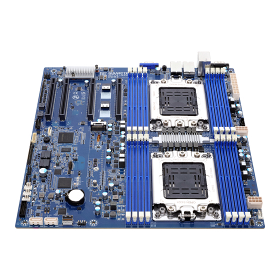
Page 5: Mp72-Hb0 Motherboard Layout
MP72-HB0 Motherboard Layout CPU0 CPU1 - 5 -... - Page 6 Item Code Description VGA1 VGA Port SW_ID1 ID Button with LED LAN2 10GbE LAN Port #2 LAN1 10GbE LAN Port #1 USB3_MLAN1 Server Management LAN Port (Top)/ USB3.0 Ports (Bottom) COM1 Serial Port ATX1 2 x 12 Pin Main Power Connector PMBUS1 PMBus Connector P12V_1...
-
Page 7: Block Diagram
Block Diagram - 7 -... - Page 8 This page left intentionally blank - 8 -...
-
Page 9: Chapter 1 Hardware Installation
Chapter 1 Hardware Installation Installation Precautions The motherboard contains numerous delicate electronic circuits and components which can become damaged as a result of electrostatic discharge (ESD). Prior to installation, carefully read the user's manual and follow these procedures: • Prior to installation, do not remove or break motherboard S/N (Serial Number) sticker or warranty sticker provided by your dealer. -
Page 10: Product Specifications
Product Specifications NOTE: We reserve the right to make any changes to the product specifications and product-related information without prior notice. E-ATX Š Form Factor 305W x 330D (mm) Š Socket Security Server Operating Properties Ampere® Altra® or Altra® Max Processor Š... - Page 11 Internal I/O 1 x 24-pin ATX main power connector Š Connectors 2 x 8-pin ATX 12V power connectors Š 2 x SlimSAS connectors Š 1 x SlimSAS vertical connector Š Socket Security Server Operating Properties 2 x 7-pin SATA connectors Š...
- Page 12 Board Aspeed® AST2600 management controller Š Management GIGABYTE Management Console (AMI MegaRAC SP-X) web interface Š Dashboard Š Security Server Operating Properties HTML5 KVM Š Sensor Monitor (Voltage, RPM, Temperature, CPU Status …etc.) Š Power Supply Sensor Reading History Data Š...
-
Page 13: Installing And Removing The Cpu
Installing and Removing the CPU Read the following guidelines before you begin to install the CPU: • Make sure that the motherboard supports the CPU. • Always turn off the computer and unplug the power cord from the power outlet before installing the CPU to prevent hardware damage. - Page 14 - 14 - Hardware Installation...
-
Page 15: Installing And Removing Memory
Installing and Removing Memory Read the following guidelines before you begin to install the memory: • Make sure that the motherboard supports the memory. It is recommended that memory of the same capacity, brand, speed, and chips be used. • Always turn off the computer and unplug the power cord from the power outlet before installing the memory to prevent hardware damage. -
Page 16: Installing And Removing The Memory Module
1-4-2 Installing and Removing the Memory Module Before installing a memory module, make sure to turn off the computer and unplug the power cord from the power outlet to prevent damage to the memory module. Be sure to install DDR4 DIMMs on to this motherboard. Follow these instructions to install a DIMM module: Insert the DIMM memory module vertically into the DIMM slot and push it down. -
Page 17: Altra Platform Ddr4 Suggest Configuration Table
1-4-4 Altra Platform DDR4 Suggest Configuration Table Memory Q’ty CPU0 CPU1 for each CPU E0 F0 G0 H0 D0 C0 B0 A0 M0 N0 O0 P0 L0 K0 J0 I0 1 DIMM 2 DIMM 4 DIMM 6 DIMM 8 DIMM - 17 - Hardware Installation... -
Page 18: Installing And Removing The M.2 Ssd Module
Installing and Removing the M.2 SSD Module Follow the steps below to install an optional M.2 SSD module on your motherboard. Step1. Insert the M.2 SSD module into the slot. Step2. Secure it with the screw, tightening as necessary to fasten the M.2 SSD module in place. Hardware Installation - 18 -... -
Page 19: Back Panel Connectors
Back Panel Connectors Serial Port Connects to serial-based mouse or data processing devices. 10/100/1000 Server Management LAN Port The LAN port provides Internet connection with data transfer speeds of 10/100/1000Mbps. This port is the dedicated LAN port for Server Management. USB 3.2 Gen1 Ports The USB port supports the USB 3.0 specification. -
Page 20: Internal Connectors
Internal Connectors CPU0 CPU1 ATX1 F_USB2 P12V_1 (for CPU0) 12) F_USB1 P12V_2 (for CPU1) 13) FP_1 SATA3 14) BP_1 SATA2 15) CON1 SYS_FAN0 16) IPMB1 SYS_FAN1 17) LED_BMC1 SYS_FAN2 18) BAT1 SYS_FAN3 10) PMBUS1 Read the following guidelines before connecting external devices: •... - Page 21 1/2/3) ATX1/P12V_1/P12V_2 (2x12 Main Power Connector and 2x4 12V Power Connector) With the use of the power connector, the power supply can supply enough stable power to all the components on the motherboard. Before connecting the power connector, first make sure the power supply is turned off and all devices are properly installed. The power connector possesses a foolproof design. Connect the power supply cable to the power connector in the correct orientation.
- Page 22 4/5) SATA3/SATA2 (SATA 6Gb/s Connectors) The SATA connectors conform to SATA 6Gb/s standard and are compatible with SATA 3Gb/s standard. Each SATA connector supports a single SATA device. Pin No. Definition 6/7/8/9) SYS_FAN0/SYS_FAN1/SYS_FAN2/SYS_FAN3 (System FAN Headers) The motherboard has four 4-pin (SYS_FAN) system fan headers. Most fan headers possess a foolproof insertion design.
- Page 23 10) PMBus Connector The Power Management Bus (PMBus) is a variant of the System Management Bus (SMBus) which is targeted at digital management of power supplies. Pin No. Definition PMBus Clock PMBus Data PMBus Alert 3.3V Sense 11/12) F_USB2/ F_USB1 (USB 3.0 Connector/ 2.0 Header) The connector/header conform to USB 2.0/ 3.0 specification. Each USB connector/header can provide two USB ports via an optional USB bracket.
- Page 24 13) FP_1 (Front Panel Header) Connect the power switch, reset switch, speaker, chassis intrusion switch/sensor and system status indicator on the chassis to this header according to the pin assignments below. Note the positive and negative pins before connecting the cables. Pin No.
- Page 25 15) CON1 (Trusted Platform Module Connector) Trusted Platform Module (TPM) is an international standard for a secure cryptoprocessor, a dedicated microcontroller designed to secure hardware through integrated cryptographic keys. 13 14 Pin No. Definition Pin No. Definition Clock P_3V3_SOC_S0 LPC_RST No Pin P_3V3_SOC_S0 SPI_MISO...
- Page 26 17) LED_BMC1 (BMC Firmware Readiness LED) State Description BMC firmware is initial Blink BMC firmware is ready AC loss 18) BAT (Battery Socket) The battery provides power to keep the values (such as BIOS configurations, date, and time information) in the CMOS when the computer is turned off. Replace the battery when the battery voltage drops to a low level, or the CMOS values may not be accurate or may be lost. •...
-
Page 27: Jumper Settings
Jumper Settings Normal Opera on (Default) Clear CMOS CLR_CMOS Clear CMOS data - 27 - Hardware Installation... -
Page 28: Chapter 2 Bios Setup
Chapter 2 BIOS Setup BIOS (Basic Input and Output System) records hardware parameters of the system in the EFI on the motherboard. Its major functions include conducting the Power-On Self-Test (POST) during system startup, saving system parameters, loading the operating system etc. The BIOS includes a BIOS Setup program that allows the user to modify basic system configuration settings or to activate certain system features. When the power is turned off, the battery on the motherboard supplies the necessary power to the CMOS to keep the configuration values in the CMOS. - Page 29 Main This setup page includes all the items of the standard compatible BIOS. Advanced This setup page includes all the items of AMI BIOS special enhanced features. (ex: Auto detect fan and temperature status, automatically configure hard disk parameters.) Chipset This setup page includes all the submenu options for configuring the function of processor, network, North Bridge, South Bridge, and System event logs. ...
-
Page 30: The Main Menu
The Main Menu Once you enter the BIOS Setup program, the Main Menu (as shown below) appears on the screen. Use arrow keys to move among the items and press <Enter> to accept or enter other sub-menu. Main Menu Help The on-screen description of a highlighted setup option is displayed on the bottom line of the Main Menu. - Page 31 Parameter Description BIOS Information Access Level Displays the privileges level information. System Project Name Displays the system project name information. Project Name Displays the motherboard project name information Project Version Displays version number of the BIOS setup utility. Build Date and Time Displays the date and time when the BIOS setup utility was created. BMC Information (Note1) BMC Firmware Version...
- Page 32 Parameter Description System Language Option: English. System Date Sets the date following the weekday-month-day-year format. System Time Sets the system time following the hour-minute-second format. BIOS Setup - 32 -...
-
Page 33: Advanced Menu
Advanced Menu The Advanced Menu displays submenu options for configuring the function of various hardware components. Select a submenu item, then press <Enter> to access the related submenu screen. BIOS Setup - 33 -... -
Page 34: Trusted Computing
2-2-1 Trusted Computing Parameter Description Configuration Enable/Disable BIOS support for security device. OS will not show security device. TCG EFI protocol and INT1A interface will not be Security Device Support available. Options available: Enable, Disable. Default setting is Enable. BIOS Setup - 34 -... -
Page 35: Acpi Settings
2-2-2 ACPI Settings Parameter Description ACPI Settings Enable/Disable BIOS ACPI auto configuration. Enable ACPI Auto Configuration Options available: Disabled, Enabled. Default setting is Enabled. Enable CPPC (Note) Options available: Disabled, Enabled. Default setting is Enabled. Enable DVFS Mode Default setting is Disabled. Enable LPI Options available: Disabled, Enabled. Default setting is Enabled. (Note) Enable Max Performance Options available: Disabled, Enabled. -
Page 36: Apei Configuration
2-2-3 APEI Configuration Description Parameter APEI Configuration Enable/Disable ACPI platform Error Interface support. APEI Enable Options available: Disabled, Enabled. Default setting is Disabled. BIOS Setup - 36 -... -
Page 37: General Watchdog Timer
2-2-4 General Watchdog Timer Description Parameter General Watchdog Timer Timeout when SCP will reset system if it doesn't receive response from ARMv8. Options available: Disable, 5 minutes, 6 minutes, 10 minutes, 15 minutes, 20 Secure Watchdog Timeout minutes. Default setting is Disable. Options available: Disable, 5 minutes, 6 minutes, 10 minutes, 15 minutes, 20 BIOS Watchdog Timeout minutes. -
Page 38: X86 Emulation Configuration
2-2-5 X86 Emulation Configuration Description Parameter X86 Emulator Configuration Enable/Disable X86 Emulator support. X86 Emulator Enable Options available: Enabled, Disabled. Default setting is Disabled. BIOS Setup - 38 -... -
Page 39: Pci Subsystem Settings
2-2-6 PCI Subsystem Settings BIOS Setup - 39 -... - Page 40 Parameter Description AMI PCI Driver Version Displays the AMI PCI Bus Driver version information PCI Settings Common for all Devices: Enable/Disable Single Root IO virtualization support. SR-IOV Support Options available: Disabled, Enabled. Default setting is Enabled. Change Settings of the following PCI Devices: Press [Enter] to configure advanced items.
- Page 41 2-2-6-1 PCI Express GEN 1 Settings Parameter Description PCI Express Device Register Settings Enable/disable PCI Express Device Relaxed Ordering. Relaxd Ordering Options available: Enabled, Disabled. Default setting is Enabled. If enabled, allows device to use 8-bit tag field as a requester. Extended Tag Options available: Enabled, Disabled. Default setting is Disabled. Enable/disable PCI Express Device No Snoop option.
- Page 42 Parameter Description If supported by hardware and set to "Enabled", the device is permitted to use CLKREQ# signal for power management of Link Clock Power Management clock in accordance to protocol defined in appropriate form factor specification. Options available: Enabled, Disabled. Default setting is Disabled. Defines number of Retry attempts software will take to retrain the Link Training Retry link if previous training attempt was unsuccessful.
- Page 43 2-2-6-2 PCI Express GEN 2 Settings Parameter Description PCI Express GEN2 Device Register Settings I n d e v i c e f u n c t i o n s t h a t s u p p o r t c o m p l e t i o n t i m e o u t programmability, allows system software to modify the completion timeout value.
- Page 44 Parameter Description If supported by hardware and set to 'Enabled', outbound AtomicOp Egress Blocking AtomicOp Requestsvia Egress Ports will be blocked. Options available: Enabled, Disabled. Default setting is Disabled. If supported by hardware and set to 'Enabled', this permits setting the number of ID-Based Ordering (IDO) bit (Attribute[2]) requests IDO Request Enable to be initiated.
-
Page 45: Info Report Configuration
2-2-7 Info Report Configuration Description Parameter Post Report Enable/disable post report support. Post Report Options available: Enabled, Disabled. Default setting is Enabled. Options available: 0,1,2,3,4,5,6,7,8,9,10, Until Press ESC. Delay Time Default setting is 1. Error Message Report Enable/disable Info error message support. Info Error Message Options available: Enabled, Disabled. -
Page 46: Usb Configuration
2-2-8 USB Configuration Parameter Description USB Configuration USB Module Version Displays the USB module version information. USB Controllers Displays the supported USB controllers. USB Devices: Displays the USB devices connected to the system. Enable/Disable the XHCI (USB 3.0) Hand-off support. XHCI Hand-off Options available: Enabled, Disabled. -
Page 47: Network Stack Configuration
2-2-9 Network Stack Configuration Parameter Description Enable/Disable the UEFI network stack. Network Stack Options available: Enabled, Disabled. Default setting is Enabled. PXE Retry Options available: Enabled, Disabled. Default setting is Disabled. (Note) Enable/Disable the Ipv4 PXE feature. Ipv4 PXE Support (Note) Options available: Enabled, Disabled. -
Page 48: Ip Configuration
2-2-10 IP Configuration Parameter Description IP Configuration Settings Provides the Options to Configure the IP Address Options available: Disabled, Every Boot, On Demand. Auto Configuration Default setting is Disabled. BIOS Setup - 48 -... -
Page 49: Nvme Configuration
2-2-11 NVMe Configuration Parameter Description NVMe controller and Drive Displays the NVMe devices connected to the system information BIOS Setup - 49 -... -
Page 50: Sata Configuration
2-2-12 SATA Configuration Parameter Description Displays the installed HDD devices information. System will automatically SATA Configuration detect HDD type. BIOS Setup - 50 -... -
Page 51: Graphic Output Configuration
2-2-13 Graphic Output Configuration Parameter Description Graphic Output Configuration Selects output device type. Output Device Type Options available: First loaded Device, Onboard Device, External Device, Specific Device. Default setting is Onboard Device. Use Onboard graphics output under OS (BMC KVM requires onboard graphics output). OS graphics output Options available: Controlled by OS, Onboard VGA. -
Page 52: Power Restore Configuration
2-2-14 Power Restore Configuration Parameter Description Specifies what state when power is re-applied after a power failure (G3 state). Power Restore Options available: Power Off, Power On, Last State. Default setting is Last State. BIOS Setup - 52 -... -
Page 53: Broadcom Netxtreme-E 2Px10Gbase-T Ocp 3.0 Ethernet
2-2-15 Broadcom NetXtreme-E 2Px10GBASE-T OCP 3.0 Ethernet Parameter Description Press [Enter] to view firmware image information. Firmware Image Menu Press [Enter] to configure advanced items. Multi-Function Mode Š – Configures the NIC Hardware Mode. – Options available: SF, NPAR 1.0. Default setting is SF. Number of VFs Per PF Š – Configures the number of Virtual Functions Per Physical Function in multiples of 8 (1-128). This field is only applicable when SR-IOV is enabled. – Default setting is 8. SR-IOV Device Configuration Menu Š... - Page 54 Description Parameter Energy Efficient Ethernet Š – Enable/Disable Energy Efficient Ethernet operation. – Options available: Enabled, Disabled. Default setting is Disabled. Operational Link Speed Š – Configures the link speed setting to be used as the default link speed for the selected port. – Default setting is AutoNeg. Support RDMA Š – Enable/Disable RDMA support for this port. –...
- Page 55 Parameter Description Setup Key Stroke Š – Configures key strokes to invoke the configuration menu. – Options available: Ctrl-S, Ctrl-B. Default setting is Ctrl-S. Banner Message Timeout Š – Selects the timeout value. (0 defaults to 4 seconds, 15 is no delay, 1-14 is timeout value in seconds) –...
- Page 56 2-2-15-1 iSCSI Boot Configuration Menu Parameter Description Press [Enter] to configure advanced items. TCP/IP Parameters via DHCP Š – Acquires TCP/IP Parameters via DHCP. – Options available: Enabled, Disabled. Default setting is Enabled. IP Autoconfiguration Š – Auto-configures the IP configuration. – Options available: Enabled, Disabled. Default setting is Enabled. iSCSI Parameters via DHCP Š...
- Page 57 Description Parameter Use TCP Timestamp Š – Enable/Disable the TCP timestamp. – Options available: Enabled, Disabled. Default setting is Disabled. Target as First HDD Š – Enable/Disable target appears as first hard disk drive (HDD) in the system. – Options available: Enabled, Disabled. Default setting is Disabled. iSCSI General Parameters LUN Busy Retry Count Š...
- Page 58 Description Parameter Boot LUN Š – Configures the Target boot LUN number (0-255). iSCSI Name Š – Configures the iSCSI name. CHAP ID iSCSI First/Second Target Š – Configures the Challenge-Handshake Authentication Protocol Parameters (continued) (CHAP) ID (up to 128 characters in length). CHAP Secret Š – Configure the Challenge-Handshake Authentication Protocol (CHAP) Secret (12 to 16 characters in length). Press [Enter] to configure advanced items.
-
Page 59: Mac Ipv4 Network Configuration
2-2-16 MAC IPv4 Network Configuration Parameter Description Indicates whether network address is configured successfully or not. Configured Options available: Enabled, Disabled. Default setting is Disabled. Options available: Enabled, Disabled. Default setting is Enabled. Enable DHCP (Note) Local IP Address Press [Enter] to configure local IP address. (Note) Press [Enter] to configure local NetMask. Local NetMask (Note) Press [Enter] to configure local Gateway Local Gateway (Note) Press [Enter] to configure local DNS servers Local DNS Servers... -
Page 60: Mac Ipv6 Network Configuration
2-2-17 MAC IPv6 Network Configuration Parameter Description Press [Enter] to configure advanced items. Displays the MAC Address information. Š Interface ID Š – The 64 bit alternative interface ID for the device. The string is colon separated. e.g. ff:dd:88:66:cc:1:2:3. DAD Transmit Count Š – The number of consecutive Neighbor solicitation messages sent Enter Configuration Menu while performing Duplicate Address Detection on a tentative address. -
Page 61: Driver Health
2-2-18 Driver Health Parameter Description Driver Health Displays health status of the drivers/controllers if installed. BIOS Setup - 61 -... -
Page 62: Chipset Setup Menu
Chipset Setup Menu Chipset Setup menu displays submenu options for configuring the function of North Bridge. Select a submenu item, then press <Enter> to access the related submenu screen. Parameter Description CPU Configuration Press [Enter] for configuration of advanced items. RAS Configuration Press [Enter] for configuration of advanced items. Memory Slot Information Press [Enter] for configuration of advanced items. Serialport console Press [Enter] for configuration of advanced items. PCIE Root Complex Configuration Press [Enter] for configuration of advanced items. BIOS Setup - 62 -... -
Page 63: Cpu Configuration
2-3-1 CPU Configuration Parameter Description CPU Configuration Number of processors/cores Displays the number of installed processor information. enabled Inter Socket Connection: Displays the Inter socket connection information. Link0/1 Controls Link speed for Inter socket connection. Inter Socket Connection Speed Options available: Default, 16GT/s, 20GT/s, 25GT/s. Default setting is Configured Default. - Page 64 Parameter Description Enable/Disable L1/L2 Prefetch for each core. L1/L2 Prefetch Options available: Enabled, Disabled. Default setting is Enabled. L1C I/D Displays the technical specifications for the installed processor Warrenty BIOS Setup - 64 -...
-
Page 65: Ras Configuration
2-3-2 RAS Configuration Parameter Description RAS Configuration Options available: Disabled, Enabled. Default setting is Disabled. Hardware EINJ Options available: Disabled, Enabled. Default setting is Disabled. DRAM EINJ No Trigger PCIe AER Firmware First Options available: Disabled, Enabled. Default setting is Disabled. Options available: Disabled, Enabled. -
Page 66: Memory Slot Information
2-3-3 Memory Slot Information Parameter Description Memory Configuration Total Memory/ Effective Displays the technical specifications for the installed memory module. Memory/ Memory Speed Enable Slave 32bit memory Options available: Disabled, Enabled. Default setting is Disabled. region Fine Granularity Refresh (FGR) Options available: 1x, 2x, 4x. Default setting is 1x. Press [Enter] to configure advanced items. - Page 67 Parameter Description Write CRC Š – Options available: Disabled, Enabled. Default setting is Memory RAS and Performance Disabled. Configuration (continued) CVE-2020-10255 mitigation Š – Options available: Disabled, Enabled. Default setting is Disabled. Press [Enter] to configure advanced items. Socket0/1 Configured Mode Š NVDIMM-N Configuration Mode Selection Š – Options available: Non-NVDIMM, Non-Hashed, Hashed, Auto. Default setting is Auto.
-
Page 68: Serialport Console
2-3-4 Serialport console Parameter Description Serialport console Serialport console for UART0 Options available: Disabled, Enabled. Default setting is Enabled. (COM1/SOL) Options available: Disabled, Enabled. Default setting is Enabled. Serialport console for UART2 BIOS Setup - 68 -... -
Page 69: Pcie Root Complex Configuration
2-3-5 PCIE Root Complex Configuration Parameter Description PCIE Root Complex Configuration PCIe Lanes Bifurcation Mode Options available: Manual, Default. Default setting is Default. Options available: Disabled, Enabled. Default setting is Disabled. SMMU Pmu On-board VGA Options available: Disabled, Enabled. Default setting is Enabled. Root Complex # Press [Enter] to view advanced items. -
Page 70: Server Management Menu
Server Management Menu Parameter Description BMC Self Test Status/ BMC Device ID/ BMC Device Revision/ Displays the technical specification of the BMC controller. BMC Firmware Revision/ IPMI Version/ BMC Interface(s) BMC Support Options available: Enabled, Disabled. Default setting is Enabled. System Event Log Press [Enter] to configure advanced items. Bmc self test log Press [Enter] to configure advanced items. -
Page 71: System Event Log
2-4-1 System Event Log Parameter Description Enabling / Disabling Options Change this item to enable or disable all features of System Event SEL Components Logging during boot. Options available: Enabled, Disabled. Default setting is Enabled. Erasing Settings Choose options for erasing SEL. Erase SEL Options available: No/Yes, On next reset/Yes, On every reset. -
Page 72: Bmc Self Test Log
2-4-2 Bmc self test log Parameter Description Log area usage = 00 out of 20 logs Erase Log Options available: Yes, On every reset/ No. Default setting is No. Options available: Clear Log, Do not log any more. Default setting is Do When log is full not log any more. -
Page 73: View Fru Information
2-4-3 View FRU Information The FRU page is a simple display page for basic system ID information, as well as System product information. Items on this window are non-configurable. (Note) The model name will vary depends on the product you purchased BIOS Setup - 73 -... -
Page 74: Bmc Network Configuration
2-4-4 BMC Network Configuration Parameter Description BMC network configuration Lan Channel 1 Selects to configure LAN channel parameters statically or dynamically (DHCP). Do nothing option will not modify any BMC network parameters Configuration Address source during BIOS phase. Options available: Unspecified, Static, DynamicBmcDhcp. Default setting is DynamicBmcDhcp. Station IP address Displays IP Address information. Displays Subnet Mask information. Subnet mask Please note that the IP address must be in three digitals, for example, 192.168.000.001. -
Page 75: Security Menu
Security Menu The Security menu allows you to safeguard and protect the system from unauthorized use by setting up access passwords. There are two types of passwords that you can set: • Administrator Password Entering this password will allow the user to access and change all settings in the Setup Utility. •... -
Page 76: Secure Boot
2-5-1 Secure Boot The Secure Boot submenu is applicable when your device is installed the Windows 8 (or above) operating ® system. Parameter Description System Mode Displays if the system is in User mode or Setup mode. Enable/ Disable the Secure Boot function. Secure Boot Options available: Enabled, Disabled. - Page 77 Parameter Description Press [Enter] to configure advanced items. Please note that this item is configurable when Secure Boot Mode is set to Custom. Factory Key Provision Š – Allows to provision factory default Secure Boot keys when system is in Setup Mode. – Options available: Enabled, Disabled. Default setting is Disabled. Restore Factory Keys Š...
- Page 78 Parameter Description Authorized TimeStamps (DBT) Š – Displays the current status of the Authorized TimeStamps Database. – Press [Enter] to configure a new DBT or load additional DBT from storage devices. Key Management – Options available: Update, Append. (continued) OsRecovery Signatures Š – Displays the current status of the OsRecovery Signature Database. –...
-
Page 79: Boot Menu
Boot Menu The Boot menu allows you to set the drive priority during system boot-up. BIOS setup will display an error message if the legacy drive(s) specified is not bootable. Parameter Description Boot Configuration Number of seconds to wait for setup activation key. 65535 (0xFFFF) Setup Prompt Timeout means indefinite waiting. Press the numeric keys to input the desired values. - Page 80 Parameter Description FIXED BOOT ORDER Priorities Press [Enter] to configure the boot priority. By default, the server searches for boot devices in the following sequence: Hard drive. Boot Option #1 / #2 / #3 / #4 / #5 CD-COM/DVD drive. USB device. Network. UEFI. UEFI Network Drive BBS Press [Enter] to configure the boot priority.
-
Page 81: Save & Exit Menu
Save & Exit Menu The Save & Exit menu displays the various options to quit from the BIOS setup. Highlight any of the exit options then press <Enter>. Parameter Description Save Options Saves changes made and closes the BIOS setup. Save Changes and Exit Options available: Yes, No. - Page 82 Parameter Description Loads the default settings for all BIOS setup parameters. Setup Defaults are quite demanding in terms of resources consumption. If you are using low-speed memory chips or other kinds of low-performance components Restore Defaults and you choose to load these settings, the system might not function properly.
-
Page 83: Bios Post Beep Code (Ami Standard)
BIOS POST Beep code (AMI standard) 2-8-1 PEI Beep Codes # of Beeps Description Memory not Installed. Memory was installed twice (InstallPeiMemory routine in PEI Core called twice) Recovery started DXEIPL was not found DXE Core Firmware Volume was not found Recovery failed S3 Resume failed Reset PPI is not available...
Need help?
Do you have a question about the MP72-HB0 and is the answer not in the manual?
Questions and answers