Table of Contents
Advertisement
Quick Links
Advertisement
Table of Contents

Related Manuals for Gigabyte MBBZ1AI


Summary of Contents for Gigabyte MBBZ1AI
- Page 1 MBBZ1AI Fusion APU E-450 processor motherboard ® User's Manual Rev. 1201...
- Page 2 GIGABYTE's prior written permission. Documentation Classifications In order to assist in the use of this product, GIGABYTE provides the following types of documentation: For detailed product information, carefully read the User's Manual.
-
Page 3: Table Of Contents
Table of Contents Box Contents ........................4 MBBZ1AI Motherboard Layout ..................5 Chapter 1 Hardware Installation ..................7 Installation Precautions ..................7 1-2 Product Specifications ..................8 Installing the Memory ..................10 1-3-1 Single Channel Memory Configuration ..............10 1-3-2 Installing a Memory ....................11 Back Panel Connectors .................. 12 Internal Connectors .................. -
Page 4: Box Contents
Box Contents MBBZ1AI motherboard Driver CD Two SATA cables I/O Shield • The box contents above are for reference only and the actual items shall depend on the product package you obtain. The box contents are subject to change without notice. -
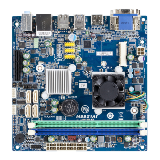
Page 5: Mbbz1Ai Motherboard Layout
MBBZ1AI Motherboard Layout - 5 -... - Page 6 Item Code Description AUDIO Audio connectors RJ45 LAN port (top) / USB 2.0 ports USB_LAN (buttom) USB2 USB 2.0 ports USB3 USB 3.0 ports HDMI HDMI port VGAVGA_DVI VGA port (top) / DVI-D port (buttom) MPCIE1X Mini PCI Express connector ATX_12V 4 pin power connector Embedded porcessor...
-
Page 7: Chapter 1 Hardware Installation
Chapter 1 Hardware Installation Installation Precautions The motherboard contains numerous delicate electronic circuits and components which can become damaged as a result of electrostatic discharge (ESD). Prior to installation, carefully read the user's manual and follow these procedures: • Prior to installation, do not remove or break motherboard S/N (Serial Number) sticker or warranty sticker provided by your dealer. -
Page 8: Product Specifications
1-2 Product Specifications Supports single AMD Fusion APU E-450 processor Š ® Supports Dual Core up to 1.65GHz Š TDP 18W Š Supports 1M Cache Š Chipset FCH Hudson-D3 chipset Š ® Memory 2 x 1.5V DDR3 slots Š Max. to 8GB (4GB x 2) Š... - Page 9 1 x 16 Mbit flash Š AMI BIOS Š Form Factor Mini ITX Form Factor; 170cm x 170cm Š * GIGABYTE reserves the right to make any changes to the product specifications and product-related information without prior notice. Hardware Installation - 9 -...
-
Page 10: Installing The Memory
Installing the Memory Read the following guidelines before you begin to install the memory: • Make sure that the motherboard supports the memory. It is recommended that memory of the same capacity, brand, speed, and chips be used. • Always turn off the computer and unplug the power cord from the power outlet before installing the memory to prevent hardware damage. -
Page 11: Installing A Memory
1-3-2 Installing a Memory Before installing a memory module, make sure to turn off the computer and unplug the power cord from the power outlet to prevent damage to the memory module. Be sure to install DDR3 DIMMs on this motherboard. Installation Step: Step 1. -
Page 12: Back Panel Connectors
Back Panel Connectors Video Port The video in port allows connect to video in, which can also apply to video loop thru function. DVI-D Port The DVI-D port supports DVI-D specifictation. Connect a monitor that supports DVI-D connectionto this port. HDMI Port The HDMI (High-Definition Multimedia Interface) provides an all-digital audio/video interface to transmit the uncompressed audio/video signals and is HDCP compliant. - Page 13 Connection/ Speed LED Activity LED Connection/Speed LED: Activity LED: State Description State Description Orange 1 Gbps data rate Blinking Data transmission or receiving is occurring Green 100 Mbps data rate No data transmission or receiving is occurring LAN Port 10 Mbps data rate • When removing the cable connected to a back panel connector, first remove the cable from your device and then remove it from the motherboard.
-
Page 14: Internal Connectors
Internal Connectors F_PANEL CPU_FAN SYS_FAN ATX_12V BATTERY F_USB2_1 CLR_CMOS F_USB2_2 JRS1 F_USB2_3 JCOMC3 F_AUDIO JCOMC4 SATAIII_0/1/2/3 JRS4 COM3 JRS5 COM4 JRS3 COM2 JRS2 COM1 USB_PWR Read the following guidelines before connecting external devices: • First make sure your devices are compliant with the connectors you wish to connect. • Before installing the devices, be sure to turn off the devices and your computer. - Page 15 1) F_PANEL (Front Panel Header) Connect the power switch, reset switch, speaker, LAN LED sensor and system status indicator on the chassis to this header according to the pin assignments below. Note the positive and negative pins be- fore connecting the cables. Pin No.
- Page 16 2/3) ATX/ATX_12V (2x2 12V Power Connector and 2x10 Main Power Connector) With the use of the power connector, the power supply can supply enough stable power to all the com- ponents on the motherboard. Before connecting the power connector, first make sure the power supply is turned off and all devices are properly installed.
- Page 17 4/5/6) F_USB_1/2/3 (USB Headers) The headers conform to USB 2.0/1.1 specification. Each USB header can provide two USB ports via an optional USB bracket. For purchasing the optional USB bracket, please contact the local dealer. F_USB_1 F_USB_2 F_USB_3 F_USB_1 F_USB_2 F_USB_3 Pin No.
- Page 18 7) F_AUDIO (Front Panel Audio Header) The front panel audio header supports Intel High Definition audio (HD) and AC'97 audio. You may connect your chassis front panel audio module to this header. Make sure the wire assignments of the module con- nector match the pin assignments of the motherboard header.
- Page 19 9/10/11/12) COM3/COM4/COM2/COM1 (Serial Port Headers) The COM headers can provide one serial port via an optional COM port cable. For purchasing the op- tional COM port cable, please contact the local dealer. COM3 COM4 COM2 COM1 COM1 COM2 Pin No. Definition Pin No.
- Page 20 13/14) CPU_FAN/SYS_FAN (CPU Fan/System Fan Headers) The motherboard has a 4-pin CPU fan header (CPU_FAN) and a 4-pin System fan header (SYS_FAN) header. Most fan headers possess a foolproof insertion design. When connecting a fan cable, be sure to connect it in the correct orientation (the black connector wire is the ground wire). The motherboard supports CPU fan speed control, which requires the use of a CPU fan with fan speed control design.
- Page 21 16) CLR_CMOS (Clearing CMOS Jumper) Use this jumper to clear the CMOS values (e.g. date information and BIOS configurations) and reset the CMOS values to factory defaults. To clear the CMOS values, place a jumper cap on the two pins to temporarily short the two pins or use a metal object like a screwdriver to touch the two pins for a few seconds.
- Page 22 18/19) JCOMC3/JCOMC4 (Serial Port #3/#4 5V/12V/RI Select Headers) 1-2 Close: 5V (Power COM) 3-4 Close: RI (STAND COM) JCOMC3 JCOMC4 5-6 Close: 12V (Power COM) 20/21/22/23) JRS4/JRS5/JRS3/JRS2 (RS232/RS422/RS485 Mode Select Jumper) JRS2 Pin No. Definition RS485_B -DCD IN RS232 -RXD OUT JRS3 JRS4 Pin No.
- Page 23 USB_PWR USB Stand-by 5V/VCC 5V Select Jumper 1-2 Close: VCC 5V. (Default setting) 2-3 Close: Stand-by 5V. Pin No. Definition Stand-by 5V - 23 - Hardware Installation...
-
Page 24: Chapter 2 Bios Setup
Chapter 2 BIOS Setup BIOS (Basic Input and Output System) records hardware parameters of the system in the CMOS on the motherboard. Its major functions include conducting the Power-On Self-Test (POST) during system startup, saving system parameters and loading operating system, etc. BIOS includes a BIOS Setup program that allows the user to modify basic system configuration settings or to activate certain system features. - Page 25 Main This setup page includes all the items in standard compatible BIOS. Advanced This setup page includes all the items of AMI BIOS special enhanced features. (ex: Auto detect fan and temperature status, automatically configure hard disk parameters.) ...
-
Page 26: The Main Menu
The Main Menu Once you enter the BIOS Setup program, the Main Menu (as shown below) appears on the screen. Use arrow keys to move among the items and press <Enter> to accept or enter other sub-menu. Main Menu Help The on-screen description of a highlighted setup option is displayed on the bottom line of the Main Menu. - Page 27 BIOS Information BIOS Vendor Display BIOS vendor information. BIOS Version Display version number of the BIOS setup utility. Core Version Display version of the processor. Compliency Display compliency information. Project Version Display version number of the project. BIOS Build Date and Time Displays the date and time when the BIOS setup utility was created.
-
Page 28: Advanced Menu
Advanced Menu The Advanced menu display submenu options for configuring the function of various hardware components. Select a submenu item, then press Enter to access the related submenu screen. BIOS Setup - 28 -... -
Page 29: Acpi Settings
2-2-1 ACPI Settings ACPI Settings Enable ACPI Auto Configuration Enable/Disable BIOS ACPI Auto Configuration. Option available: Enabled/Disabled. Default setting is Disabled. ACPI Sleep State Select the highest ACPI sleep state the system will enter, when the suspend button is pressed. Suspend Disabled/S1 only (CPU Stop Clock)/S3 only (Suspend to RAM). Default setting is S3 only (Suspend to RAM). - Page 30 2-2-2 CPU Configuration BIOS Setup - 30 -...
-
Page 31: Cpu Configuration
CPU Configuration PSS Support (Performance Support States/P-states Support) Enable/Disable PSS support. Options available: Enabled/Disabled. Default setting is Disabled. PSTATE Adjustment P-states level adjustment. Options available: PState 0/PState 1/PState 2/PState 3/PState 4/PState 5/PState 6/PState 7/PState 8. Default setting is PState 0. NX Mode This BIOS feature is a toggle for AMD processor's No Execute feature. -
Page 32: Sata Configuration
2-2-3 SATA Configuration IDE Configuration OnChip SATA Type Select the on chip SATA type. IDE Mode: When set to IDE, the SATA controller disables its AHCI function and runs in the IDE emulation mode. AHCI Mode: When set to AHCI,the SATA controller enables its AHCI functionality. Options available: IDE/AHCI/Disabled. -
Page 33: Usb Configuration
2-2-4 USB Configuration USB Configuration USB Device Dispay the connected USB devices information. Legacy USB Support Enables or disables support for legacy USB devices. Options available: Auto/Enabled/Disabled. Default setting is Enabled. USB Mass Storage Drive Support Enables/Disable USB Mass Storage Drive Support. Options available: Enabled/Disabled. - Page 34 2-2-5 F81214 First Super IO Configuration BIOS Setup - 34 -...
-
Page 35: F81214 First Super Io Configuration
F81214 First Super IO Configuration Display the mode name of Super IO chip. F81214 Serial Port 1/2 Configuration Press [Enter] to enter advanced meun for serial port 1 and serial port 2 settings. Serial Port When enabled allows you to configure the serial port settings. When set to Disabled, displays no configuration for the serial port. - Page 36 2-2-6 F81214 Second Super IO Configuration BIOS Setup - 36 -...
-
Page 37: F81214 Second Super Io Configuration
F81214 Second Super IO Configuration F81214 Second Super IO Chip Display the mode name of Super IO chip. F81214 Serial Port 3/4 Configuration Press [Enter] to enter advanced meun for serial port 2 and serial port 4 settings. Serial Port When enabled allows you to configure the serial port settings. When set to Disabled, displays no configuration for the serial port. -
Page 38: Network Stack
2-2-7 Network Stack Network stack Enable/Disable the network stack (PXE and UEFI). Option available: Enabled/Disabled. Default setting is Disabled. BIOS Setup - 38 -... -
Page 39: Chipset Menu
Chipset Menu Integrated Graphics Configure the onboard integrated graphic device. Options available: Auto/Disabled/Force. Default setting is Auto. UMA Frame buffer Size (Note) Configure the UMA frame buffer size for onboard integrated graphic device. Please note that this item appears when the Integrated Graphics is set to force. Options available: 32M/64M/128M256M/512M/1G/2G. - Page 40 LAN MAC Address Display the information of LAN1 MAC address. Erp Function Enable/Disable Erp support function. Options available: Enabled/Disabled. Default setting is Enabled. SB Clock Spread Spectrum Enable/Disable South Bridge Clock Spread Spectrum function. Options available: Enabled/Disabled. Default setting is Enabled. - 40 - BIOS Setup...
-
Page 41: Sb Hardware Monitor
2-3-1 SB Hardware Monitor CPU FAN Fail Detect Enable CPU Fan Stop Warning function. Option available: Enabled/Disabled. Default setting is Enabled. System FAN Fail Detect Enable System Fan Stop Warning function. Option available: Enabled/Disabled. Default setting is Disabled. CPU/System Fan Speed (RPM) Displays current CPU/System fan speed. -
Page 42: Boot Menu
Boot Menu The Boot menu allows you to set the drive priority during system boot-up. BIOS setup will display an error message if the drive(s) specified is not bootable. BIOS Setup - 42 -... -
Page 43: Setup Prompt Timeout
Boot Configuration Setup Prompt Timeout Press <+> and <-> keys to adjust the desired number. Bootup NumLock State Allows you to select power-on state for NumLock function. Options available: On/Off. Default setting is On. Quiet Boot This BIOS feature determines if the BIOS should hide the normal POST message with the motherboard or system manufacturer's full-screen. -
Page 44: Csm Parameters
2-4-1 CSM parameters CSM parameters Press Enter to configure the advanced items. CSM (Compatibility Support Module) Launch Enable/Disable Compatibility Support Module (CSM) launch. Options available: Enabled/Disabled. Default setting is Enabled. • The following five items appears and configurable when the Launch CSM is set to Enabled. •... - Page 45 Other PCI device ROM priority For PCI devices other than Network, Mass storage or Video device, defines which OpROM to launch. Options available: UEFI OpROM/Legacy OpROM. Default setting is UEFI OpROM. - 45 - BIOS Setup...
-
Page 46: Security Menu
Security Menu The Security menu allows you to safeguard and protect the system from unauthorized use by setting up ac- cess passwords. There are two types of passwords that you can set: • Adminstrator Password Entering this password will allow the user to access and change all settings in the Setup Utility. •... -
Page 47: Secure Boot Menu (Optional)
2-5-1 Secure Boot menu (Optional) The Secure Boot Menu appears when your device is installed the Windows 8 operatin system. ® Secure Boot menu Platform Mode Display the System Platform Mode State. Secure Boot Display the status of Secure Boot. Secure Boot Control Enable/Disable Secure Boot function. -
Page 48: Image Execution Policy
2-5-1-1 Image Execution policy Internal FV Image Execution Policy per device path on Security Violation. Options available: Always Execute/Always Deny/Allow Execute/Defer Execute/ Deny Execute/ Query User. Default setting is Deny Execute. Option ROM Image Execution Policy per device path on Security Violation. Options available: Always Execute/Always Deny/Allow Execute/Defer Execute/ Deny Execute/ Query User. -
Page 49: Key Management
2-5-1-2 Key Management Key Management This item appears only when the Secure Boot Mode is set to Custom. Factory Default Key Provisioning Force the system to Setup Mode. This will clear all Secure Boot Variables such as Platform Key (PK), Key-exchange Key (KEK), Authorized Signature Database (db), and Forbidden Signaures Database (dbx). - Page 50 Authorized Signature Database (DB) Display the status of Authorized Signature Database. Set new DB Press [Enter] to configure a new db. Delete DB Press [Enter] to delete the db from your system. Append Var to DB Press [Enter] to load additional db from a storage devices. Forbidden Signature Database (DBX) Display the status of Forbidden Signature Database.
-
Page 51: Save & Exit Menu
Save & Exit Menu The Exit menu displays the various options to quit from the BIOS setup. Highlight any of the exit options then press Enter. Save Changes and Exit Saves changes made and close the BIOS setup and exit system setup. Options available: Yes/No. -
Page 52: Restore User Defaults
Save as User Defaults Press <Enter> on this item and then press the <Y> key to save as user default settings. Options available: Yes/No. Restore User Defaults Press <Enter> on this item and then press the <Y> key to restore user default settings. Options available: Yes/No.
Need help?
Do you have a question about the MBBZ1AI and is the answer not in the manual?
Questions and answers