Table of Contents
Advertisement
Quick Links
Advertisement
Table of Contents

Related Manuals for Gigabyte MATMH81


Summary of Contents for Gigabyte MATMH81
- Page 1 MATMH81 Intel Socket LGA1150 processor motherboard ® User's Manual Rev. 1002...
- Page 2 GIGABYTE's prior written permission. Documentation Classifications In order to assist in the use of this product, GIGABYTE provides the following types of documentation: For detailed product information, carefully read the User's Manual.
-
Page 3: Table Of Contents
Table of Contents Box Contents ........................4 MATMH81 Motherboard Layout ..................5 Block Diagram .........................8 Chapter 1 Hardware Installation ..................9 Installation Precautions ..................9 1-2 Product Specifications ..................10 Installing the CPU and CPU Cooler ............... 12 1-3-1 Installing the CPU ....................12 1-3-2 Installing the CPU Cooler ..................14... -
Page 4: Box Contents
Box Contents Motherboard Driver CD I/O Shield • The box contents above are for reference only and the actual items shall depend on the product package you obtain. The box contents are subject to change without notice. • The motherboard image is for reference only. - 4 -... -
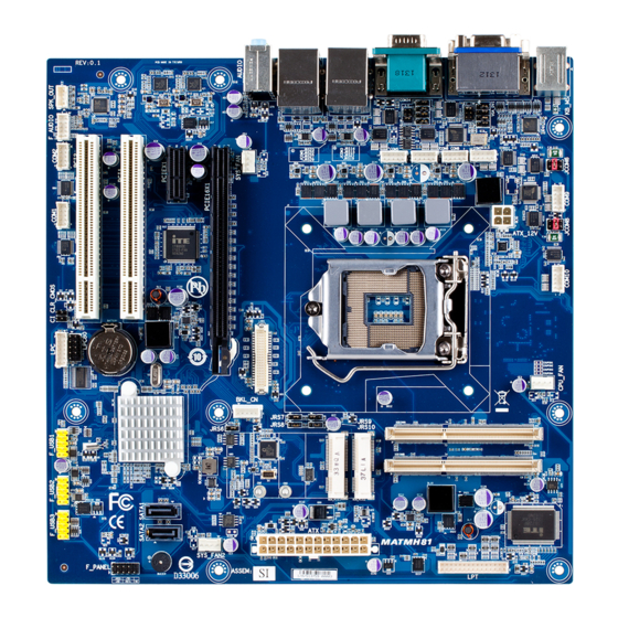
Page 5: Matmh81 Motherboard Layout
MATMH81 Motherboard Layout 47 48 49 50 51 - 5 -... - Page 6 Item Code Description AUDIO Audio connectors RJ45 LAN port (top) / USB 2.0 ports USB_LAN2 (buttom) RJ45 LAN port (top) / USB 2.0 ports USB_LAN1 (buttom) COM34 Serial ports VGA_DVI VGA port (top)/DVI port (buttom) JCOM5/JRS23/JRS22/JRS27/ RS232/RS422/RS485 Select Jumper JRS29 for COM4 COM5 Serial port cable connector #5...
- Page 7 Item Code Description GPIO_CNT GPIO connector F_USB3 Front USB 2.0 header #3 F_USB2 Front USB 2.0 header #2 F_USB1 Front USB 2.0 header #1 BATTERY Battery socket LPC connector Case open intrusion header CLR_CMOS Clear CMOS jumper COM1 Serial port cable connector #1 COM2 Serial port cable connector #2 F_AUDIO...
-
Page 8: Block Diagram
Block Diagram - 8 -... -
Page 9: Chapter 1 Hardware Installation
Chapter 1 Hardware Installation Installation Precautions The motherboard contains numerous delicate electronic circuits and components which can become damaged as a result of electrostatic discharge (ESD). Prior to installation, carefully read the user's manual and follow these procedures: • Prior to installation, do not remove or break motherboard S/N (Serial Number) sticker or warranty sticker provided by your dealer. -
Page 10: Product Specifications
1-2 Product Specifications Supports Intel Gen 4 Core processors in Socket LGA1150 Š ® Support Up to 85W Š L3 cache varies with CPU Š Chipset Intel H81 Express chipset Š ® Memory 2 x SO-DIMM slots support DDR3 1600/1333MHz Š Support up 16GB Š... - Page 11 CPU/system cooler you install. BIOS AMI BIOS Š Form Factor uATX Form Factor; 9.6 inch x 9.6 inch Š GIGABYTE reserves the right to make any changes to the product specifications and product-related information without prior notice. - 11 - Hardware Installation...
-
Page 12: Installing The Cpu And Cpu Cooler
Installing the CPU and CPU Cooler Read the following guidelines before you begin to install the CPU: • Make sure that the motherboard supports the CPU. • Always turn off the computer and unplug the power cord from the power outlet before installing the CPU to prevent hardware damage. - Page 13 B. Follow the steps below to correctly install the CPU into the motherboard CPU socket. Before installing the CPU, make sure to turn off the computer and unplug the power cord from the power outlet power plug to prevent any damage to prevent damage to the CPU. Step 1: Step 2: Gently press the CPU socket lever handle down...
-
Page 14: Installing The Cpu Cooler
1-3-2 Installing the CPU Cooler Follow the steps below to correctly install the CPU cooler on the motherboard. (The following procedure uses Intel boxed cooler as the example cooler.) ® Male Push Direction of the Arrow Sign on The Top the Male Push of Female Push Pin... -
Page 15: Installing The Memory
Installing the Memory Read the following guidelines before you begin to install the memory: • Make sure that the motherboard supports the memory. It is recommended that memory of the same capacity, brand, speed, and chips be used. • Always turn off the computer and unplug the power cord from the power outlet before installing the memory to prevent hardware damage. -
Page 16: Back Panel Connectors
Back Panel Connectors PS/2 Keyboard and PS/2 Mouse Connector To install a PS/2 port keyboard and mouse, plug the mouse to the upper port (green) and the keyboardto the lower port (purple). Video Port The video in port allows connect to video in, which can also apply to video loop thru function. DVI-D Port The DVI-D port supports DVI-D specifictation. Connect a monitor that supports DVI-D connection to this port. Serial Port Connects to serial-based mouse or data processing devices. RJ-45 LAN Port The Gigabit Ethernet LAN port provides Internet connection at up to 1 Gbps data rate. The following describes the states of the LAN port LEDs. -
Page 17: Internal Connectors
Internal Connectors JCOM8 ATX_12V COM9 SATA1/SATA2 COM10 CPU_FAN F_AUDIO SYS_FAN SPK_OUT SYS_FAN2 GPIO_CNT F_USB1 F_USB2 F_PANEL F_USB3 LVDS COM1 JRS6 COM2 JRS7 JCOM3/JRS14/JRS15/JRS21/JRS19 JRS8 COM5 JRS9 JCOM5/JRS23/JRS22/JRS27/JRS29 JRS10 COM6 BKL_CN JCOM6 BATTERY COM7 CLR_CMOS COM8 Hardware Installation - 17 -... - Page 18 Read the following guidelines before connecting external devices: • First make sure your devices are compliant with the connectors you wish to connect. • Before installing the devices, be sure to turn off the devices and your computer. Unplug the power cord from the power outlet to prevent damage to the devices. • After installing the device and before turning on the computer, make sure the device cable has been securely attached to the connector on the motherboard. - 18 - Hardware Installation...
- Page 19 al / 1/2) ATX/ATX_12V (2x2 12V Power Connector and 2x12 Main Power Connector) With the use of the power connector, the power supply can supply enough stable power to all the components on the motherboard. Before connecting the power connector, first make sure the power supply is turned off and all devices are properly installed.
- Page 20 3) SATA1/SATA2 (SATA 6Gb/s Connectors) The SATA1 and SATA2 connectors conform to SATA 6Gb/s standard and are compatible with SATA 3Gb/s standard. Each SATA connector supports a single SATA device. SATA1 SATA2 Pin No. Definition SATA1 SATA2 4/5/6) CPU_FAN/SYS_FAN (CPU Fan/System Fan Headers) The motherboard has one 4-pin CPU fan header (CPU_FAN), and two 4-pin (SYS_FAN) system fan headers. Most fan headers possess a foolproof insertion design. When connecting a fan cable, be sure to connect it in the correct orientation (the black connector wire is the ground wire).
- Page 21 F_PANEL 7/8/9) F_USB1/F_USB2/F_USB3 (USB Headers) The headers conform to USB 2.0 specification. Each USB header can provide two USB ports via an optional USB bracket. For purchasing the optional USB bracket, please contact the local dealer. PWR_LED F_USB CLR_CMOS BIOS_WP CLR_CMOS BIOS_WP SUR_CEN F_USB1 F_USB2 F_USB3 CLR_PWD F_USB1 F_USB2 F_USB3 MODEM Pin No. Definition Pin No. Definition Pin No. Definition Power (5V)
- Page 22 10/11/13/15/17/18/20/21) COM1/COM2/COM5/COM6/COM7/COM8/COM9/COM10 (Serial Port Cable Connectors) The COM header can provide one serial port via an optional COM port cable. For purchasing the optional COM port cable, please contact the local dealer. COM8 COM7 COM1 COM9 COM2 COM10 COM2 COM5 COM6 COM1 COM8 COM7 COM9 COM10 COM5 COM6 COM1 COM2 COM5...
- Page 23 12) JCOM3/JRS14/JRS15/JRS21/JRS19 (RS232/RS422/RS485 Select Header for Serial Port 3) JCOM3 JRS14 JRS15 JRS21 JRS19 1-2 Close: RS422/RS485 2-3 Close: RS232 (Default setting) 1-2 Close: RS232 Pin No. Definition RXD232 RXD3 RXD422 3-4 Close: RS422 RXD3 RXD485 RXD3 5-6 Close: RS485 - 23 - Hardware Installation...
- Page 24 14) JCOM5/JRS23/JRS22/JRS27/JRS29 (RS232/RS422/RS485 Select Header for Serial Port 4) JCOM5 JRS23 JRS22 JRS27 JRS29 1-2 Close: RS422/RS485 2-3 Close: RS232 (Default setting) 1-2 Close: RS232 Pin No. Definition RXD232 RXD4 RXD422 3-4 Close: RS422 RXD4 RXD485 RXD4 5-6 Close: RS485 - 24 - Hardware Installation...
- Page 25 16/19) JCOM6/JCOM8 (5V/12V/RI Signal Select Header for Serial Port 9/10) 1-2 Close: 5V (Power COM) 3-4 Close: RI (STAND COM) JCOM6 5-6 Close: 12V (Power COM) JCOM8 Pin No. Definition Pin No. Definition RI9-/5V/12V RI10-/5V/12V NRI9- NRI10- RI9-/5V/12V RI10-/5V/12V +12V +12V RI9-/5V/12V RI10-/5V/12V 22) F_AUDIO (Front Panel Audio Header) The front panel audio header supports Intel High Definition audio (HD) and AC'97 audio. You may connect...
- Page 26 23) SPK_OUT (Audio Amplifier Connector) Pin No. Definition OUT_R+ OUT_R- OUT_L- OUT_L+ 24) GPIO_CNT (GPIO Connector) Pin No. Definition GPIO1 GPIO68 GPIO6 GPIO69 GPIO7 GPIO70 GPIO17 GPIO71 SMBCLK SMBDATA - 26 - Hardware Installation...
- Page 27 25) LPT (LPT Connector) Pin No. Definition Pin No. Definition STB- AFD- INIT- ACK- BUSY ERR- SLIN- SLCT Hardware Installation - 27 -...
- Page 28 26) F_PANEL (Front Panel Header) Connect the power switch, reset switch, speaker, chassis intrusion switch/sensor and system status indicator on the chassis to this header according to the pin assignments below. Note the positive and negative pins before connecting the cables. Pin No. Signal Name Definition Hard Disk LED Signal anode (+)
- Page 29 27) LVDS (LVDS Headers) LVDS stands for Low-voltage differential signaling, which uses high-speed analog circuit techniques to provide multigigabit data transfers on copper interconnects and is a generic interface standard for high-speed data transmission. Pin No. Definition Pin No. Definition VCC3 A5P_C A4P_C VCC3 A5M_C A4M_C SPC0 SPD0 A7P_C A6P_C A1P_C A7M_C A0P_C...
- Page 30 28/29/30/31/32) JRS9/JRS10/JRS8/JRS7/JRS6 (LVDS Enable Jumpers) JRS6 Pin No. Definition EDP_DDC_DATA_C EDP_DDC_DATA Jumper Setting forJRS6: 1-2 Close: Enable LVDS 2-3 Close: Disable LVDS JRS7 JRS8 JRS9 JRS8 JRS9 JRS6 JRS10 Pin No. Definition Pin No. Definition VCC3 VCC3 CGPIO 1 CGPIO 2 JRS7 JRS10 Pin No. Definition Pin No. Definition VCC3...
- Page 31 33) BLK_CN (LCD Inverter Connector) Pin No. Definition PWM_OUT ENABKL +12V 34) BATTERY (Battery Scoket) The battery provides power to keep the values (such as BIOS configurations, date, and time information) in the CMOS when the computer is turned off. Replace the battery when the battery voltage drops to a low level, or the CMOS values may not be accurate or may be lost. • Always turn off your computer and unplug the power cord before replacing the battery. •...
- Page 32 35) CLR_CMOS (Clearing CMOS Jumper) Use this jumper to clear the CMOS values (e.g. date information and BIOS configurations) and reset the CMOS values to factory defaults. To clear the CMOS values, place a jumper cap on the two pins to temporarily short the two pins or use a metal object like a screwdriver to touch the two pins for a few seconds.
-
Page 33: Chapter 2 Bios Setup
Chapter 2 BIOS Setup BIOS (Basic Input and Output System) records hardware parameters of the system in the CMOS on the motherboard. Its major functions include conducting the Power-On Self-Test (POST) during system startup, saving system parameters and loading operating system, etc. BIOS includes a BIOS Setup program that allows the user to modify basic system configuration settings or to activate certain system features. When the power is turned off, the battery on the motherboard supplies the necessary power to the CMOS to keep the configuration values in the CMOS. To access the BIOS Setup program, press the <DEL> key during the POST when the power is turned on. - Page 34 Main This setup page includes all the items in standard compatible BIOS Advanced This setup page includes all the items of AMI BIOS special enhanced features. (ex: Auto detect fan and temperature status, automatically configure hard disk parameters.) Chipset Northbridge and Southbridge additional features configuration. Boot This setup page provides items for configuration of boot sequence. Security Change, set, or disable supervisor and user password. Configuration supervisor password allows you to restrict access to the system and BIOS Setup. A supervisor password allows you to make changes in BIOS Setup.
-
Page 35: The Main Menu
The Main Menu Once you enter the BIOS Setup program, the Main Menu (as shown below) appears on the screen. Use arrow keys to move among the items and press <Enter> to accept or enter other sub-menu. Main Menu Help The on-screen description of a highlighted setup option is displayed on the bottom line of the Main Menu. Submenu Help While in a submenu, press <F1> to display a help screen (General Help) of function keys available for the menu. Press <Esc> to exit the help screen. Help for each item is in the Item Help block on the right side of the submenu. • When the system is not stable as usual, select the Restore User Defaults item to set your sys- tem to its defaults. - Page 36 BIOS Information BIOS Version Display version number of the BIOS setup utility. BIOS Vendor Display BIOS vendor information. Core Version Display version of the processor. Compliency Display compliency information. Project Version Display version number of the project. BIOS Build Date and Time Displays the date and time when the BIOS setup utility was created.
-
Page 37: Advanced Menu
Advanced Menu The Advanced menu display submenu options for configuring the function of various hardware components. Select a submenu item, then press Enter to access the related submenu screen. Wake On Lan from S5 Enable/Disable LAN wake on in S5 Option avaiable: Enabled/Disabled. Default setting is Enabled. - 37 - BIOS Setup... -
Page 38: Acpi Settings
2-2-1 ACPI Settings ACPI Settings ACPI Sleep State Select the highest ACPI sleep state the system will enter, when the suspend button is pressed. Suspend Disabled/S1 only (CPU Stop Clock)/S3 only (Suspend to RAM). Default setting is S3 only (Suspend to RAM). BIOS Setup - 38 -... -
Page 39: S5 Rtc Wake Settings
2-2-2 S5 RTC Wake Settings Wake system with Fixed Time Enable/Disable system wake on alarm event. When this item is enabled, system will wake on the Date:Hour:Mintues:Seconds when specified time is defined. Option available: Enabled/Disabled. Default setting is Disabled. Wake up Date/hour/mintue/second (Note) Press [Enter] to configure the system wake up time. (Note) Advanced items prompt when this item is defined. - 39 - BIOS Setup... -
Page 40: Trusted Computing (Optional)
2-2-3 Trusted Computing (Optional) Configuration Security Device Support Enable/Disable BIOS support for security device. O.S will not show security device. TCG EFI protocol and INT1A interface will not be available. Options available: Enabled/Disabled. Default setting is Disabled. Current Status Information Display current TPM status information. -
Page 41: Cpu Configuration
2-2-4 CPU Configuration CPU Configuration CPU Type/Signature/Microcode Patech/Max CPU Speed/Min CPU Speed/CPU Speed/ Processor Cores/Intel HT Technology/Intel VT-x Technology/Intel SMX Technology/ 64-bit Displays the technical specifications for the installed processor. Cache Information L1 Data Cache / L1 Code Cache / L2 Cache / L3 Cache Displays the technical specifications for the installed processor. Active Processor Cores (Note) Allows you to determine whether to enable all CPU cores. - Page 42 Intel Virtualization Technology Select whether to enable the Intel Virtualization Technology function. VT allows a single platform to run multiple operating systems in independent partitions. Options available: Enabled/Disabled. Default setting is Enabled. EIST (Enhanced Intel SpeedStep Technology) Conventional Intel SpeedStep Technology switches both voltage and frequency in tandem between high and low levels in response to processor load.
-
Page 43: Sata Configuration
2-2-5 SATA Configuration SATA Mode Selection Select the on chip SATA type. IDE Mode: When set to IDE, the SATA controller disables its AHCI functions and runs in the IDE emulation mode. AHCI Mode: When set to AHCI,the SATA controller enables its AHCI functionality. Options available: IDE/AHCI. Default setting is AHCI. Serial ATA Port 1/Serial ATA Port 2/Serial ATA Port mSATA The category identifies Serial ATA and mSATA types of hard disk that are installed in the computer. System will automatically detect HDD type. Note that the specifications of your drive must match with the drive table. The hard disk will not work properly if you enter improper information for this category. -
Page 44: Usb Configuration
2-2-6 USB Configuration USB Configuration Legacy USB Support Enables or disables support for legacy USB devices. Options available: Auto/Enabled/Disabled. Default setting is Enabled. USB30. Support Enables/Disable USB3.0 (XHCI) controller support. Options available: Enabled/Disabled. Default setting is Enabled. XHCI Hand-off Enable/Disable XHCI (USB 3.0) Hand-off support. Options available: Enabled/Disabled. -
Page 45: H/W Monitor
2-2-7 H/W Monitor Press Enter to view the Hardware Monitor screen which displays a real-time record of the CPU/system tem- perature, and fan speed, Items on this window are non-configurable. CPU/System FAN/System FAN 2 Fail Detect Enable CPU/System Fan Fail detection. Option available: Enabled/Disabled. Default setting for CPU FAN is Enabled. Default setting for System FAN and System FAN2 are Enabled. - Page 46 2-2-8 Super I/O Configuration (COM 1/2, LPT) BIOS Setup - 46 -...
- Page 47 - 47 - BIOS Setup...
-
Page 48: Super I/O Configuration (Com 1/2, Lpt)
Super I/O Configuration (COM 1/2, LPT) Super I/O Chip Display the model name of Super IO chip. Serial Port 1/2/Parallel Port Configuration Serial Port 1/Serial Port 2 When enabled allows you to configure the serial port settings. When set to Disabled, displays no configuration for the serial port. Options available: Enabled/Disabled. Default setting is Enabled. Device Settings Display the Serial Port 1/2 base I/O addressand IRQ. Parallel Port When enabled allows you to configure the parallel port setting. -
Page 49: F81216 Second Super I/O Configuration (Com 3/4/5/6)
2-2-9 F81216 Second Super I/O Configuration (COM 3/4/5/6) - 49 - BIOS Setup... - Page 50 BIOS Setup - 50 -...
- Page 51 Super I/O Configuration (COM 3/4/5/6) F81216 Second Super I/O Chip Display the model name of Super IO chip. Serial Port 3/4/5/6 Configuration Serial Port 3/Serial Port 4/Serial Port 5/Serial Port 6 When enabled allows you to configure the serial port settings. When set to Disabled, displays no configuration for the serial port. Options available: Enabled/Disabled. Default setting is Enabled. Device Settings Display the Serial Port 3/4/5/6 base I/O addressand IRQ. - 51 - BIOS Setup...
-
Page 52: F81216 Third Super I/O Configuration (Com 7/8/9/10)
2-2-10 F81216 Third Super I/O Configuration (COM 7/8/9/10) BIOS Setup - 52 -... - Page 53 - 53 - BIOS Setup...
- Page 54 Super I/O Configuration (COM 7/8/9/10) F81216 Third Super I/O Chip Display the model name of Super IO chip. Serial Port 7/8/9/10 Configuration Serial Port 7/Serial Port 8/Serial Port 9/Serial Port 10 When enabled allows you to configure the serial port settings. When set to Disabled, displays no configuration for the serial port. Options available: Enabled/Disabled. Default setting is Enabled. Device Settings Display the Serial Port 7/8/9/10 base I/O addressand IRQ. BIOS Setup - 54 -...
-
Page 55: Intel(R) Smart Connect Technology
2-2-11 Intel(R) Smart Connect Technology ISCT Support Enable/Disable Intel Smart Connect Technology (ISCT) function. Options available: Enabled/Disabled. Default setting is Enabled. ISCT Notification Control Enable/Disable ISCT Notification Control function. Options available: Enabled/Disabled. Default setting is Enabled. ISCT WLAN Power Control Enable/Disable ISCT WLAN Power Control function. Options available: Enabled/Disabled. -
Page 56: Network Stack
2-2-12 Network Stack Network stack Enable/Disable UEFI network stack. Options available: Enabled/DIsabled. Default setting is Disabled. Ipv4 PXE Support Enable/Disable Ipv4 PXE Support. Options available: Enabled/DIsabled. Default setting is Disabled. Ipv6 PXE Support Enable/Disable Ipv6 PXE Support. Options available: Enabled/DIsabled. Default setting is Disabled. This item appears when Network Stack is set to Enabled. -
Page 57: Chipset Menu
Chipset Menu Restore AC Power Loss This option provides user to set the mode of operation if an AC / power loss occurs. Power On: System power state when AC cord is re-plugged. Power Off: Do not power on system when AC power is back. Last State: Set system to the last sate when AC power is removed. - Page 58 Wake On Ring Enable/Disable Wake On Ring function. Options available: Enabled/Disabled. Default setting is Enabled. VT-d Enable/Disable Intel Virtualization Technology for Directed I/O (VT-d) feature. Options available: Enabled/DIsabled. Default setting is Enabled. Initate Graphic Adapter Configure the primary display device. Options available: IGD/PEG/IGD. Default setting is PEG/IGD. Primary IGFX Boot Display Select the Video device which will be activated during POST.
-
Page 59: Boot Menu
Boot Menu The Boot menu allows you to set the drive priority during system boot-up. BIOS setup will display an error message if the drive(s) specified is not bootable. Boot Configuration Bootup NumLock State Enable or Disable Bootup NumLock function. Options available: On/Off. Default setting is On. Screen Logo Show Enable/Disable showing Screen Logo during system boot. - Page 60 UEFI device. Hard drive. CSM parameters Press Enter to configure the advanced items. BIOS Setup - 60 -...
-
Page 61: Csm Parameters
2-4-1 CSM Parameters CSM (Compatibility Support Module) Launch Enable/Disable Compatibility Support Module (CSM) launch. Options available: Enabled/Disabled. Default setting is Enabled. • The following five items appears and configurable when the Launch CSM is set to Enabled. • If the Launch CSM is set to Disabled, the following five items will not be able to support Legacy mode. Boot option filter Determines which devices system will boot to. Options available: UEFI and Legacy/Legacy only/UEFI only. -
Page 62: Security Menu
Security Menu The Security menu allows you to safeguard and protect the system from unauthorized use by setting up ac- cess passwords. There are two types of passwords that you can set: • Adminstrator Password Entering this password will allow the user to access and change all settings in the Setup Utility. •... -
Page 63: Secure Boot Menu
2-5-1 Secure Boot menu System Mode Display the System Mode state. Secure Boot Display the System Mode State. Secure Boot Support Secure Boot requires all the applications that are running during the booting process to be pre-signed with valid digital certificates. This way, the system knows all the files being loaded before Windows 8 loads and gets to the login screen have not been tampered with. -
Page 64: Key Management
2-5-1-1 Key Management Key Management This item appears only when the Secure Boot Mode is set to Custom. Factory Default Key Provisioning Force the system to Setup Mode. This will clear all Secure Boot Variables such as Platform Key (PK), Key-exchange Key (KEK), Authorized Signature Database (db), and Forbidden Signaures Database (dbx). Options available: Enabled/Disabled. Default setting is Disabled. Enroll All Factory Default Keys Press [Enter] to enroll all factory default keys. Save All Secure Boot Variables Press [Enter] to save all Secure Boot Variables. - Page 65 Set new KEK Press [Enter] to configure a new KEK. Append Var to KEK Press [Enter] to load additional KEK from a storage devices for an additional db and dbx management. Authorized Signature Database (DB) Display the status of Authorized Signature Database. Delete DB Press [Enter] to delete the db from your system. Set new DB Press [Enter] to configure a new db.
-
Page 66: Exit Menu
Exit Menu The Exit menu displays the various options to quit from the BIOS setup. Highlight any of the exit options then press Enter. Save Changes and Exit Saves changes made and close the BIOS setup. Options available: Yes/No. Discard Changes and Exit Discards changes made and close the BIOS setup.
Need help?
Do you have a question about the MATMH81 and is the answer not in the manual?
Questions and answers