Table of Contents
Advertisement
Quick Links
1 2
3
30
29
31
33
28
32
27
35
26
36
25
37
24
34
38
23
22
21
20
19
18
17
16
ATX Power/ 电源
24
13
1
12
1
No.
Pin Define
No.
Pin Define
CPU/System FAN/
1
3.3V
13
3.3V
2
3.3V
14
-12V
3
GND
15
GND
4
4
+5V
16
PS_ON
5
GND
17
GND
6
+5V
18
GND
1
7
GND
19
GND
8
Power Good
20
-5V
9
5VSB
21
+5V
10
+12V
22
+5V
4
11
+12V
23
+5V
12
3.3V
24
GND
Chassis Intrusion Alert Header
3
4
No.
Pin Define
No.
Pin Define
Open: Normal operation.
1
GND
3
+12V
2
GND
4
+12V
1
2
Closed: Active chassis intrustion alert.
Front Panel Header/ 前面板
2
24
1
23
No.
Pin Define
No.
Pin Define
1
Power LED+
2
5V Standby
4
ID LED+
3
No Pin
6
ID LED-
5
Power LED-
8
System Status LED+
7
HDD LED+
10
System Status LED-
9
HDD LED-
11
Power Button
12
LAN1 Active LED+
14
LAN1 Active LED-
13
GND
16
SMBus Data
15
Reset Button
18
SMBus Clock
17
GND
20
Case Open
19
ID Button
22
LAN2 Active LED
21
GND
24
LAN2 Active LED-
23
NMI Switch-
PN
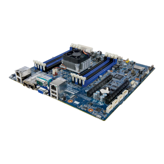
MP30-AR0/MP30-AR1 Quick Reference Guide/ 快速测试参考指南
No.
Code
4
5 6 7
1
LED_STA
2
USB2_MLAN
3
VGA1_COM1
4
SFP+_1_2
5
LAN1_2
6
SW_PWR
7
SW_ID
8
CPU_FAN
9
DIMM_P0_A0
8
10
DIMM_P0_A1
11
DIMM_P0_B0
12
DIMM_P0_B1
13
CPU0
14
P12V_AUX
15
ATX1
9
16
SYS_FAN1
17
FP_1
10
18
SYS_FAN2
19
PMBUS
11
20
CLR_CMOS
13
12
14
15
IPMB
SATA Connector/SATA
7
No.
Pin Define
No.
Pin Define
No.
1
Clock
3
1
GND
5
2
GND
2
TXP
6
3
Data
3
TXN
7
4
GND
风扇
1
1
BMC Firmware Readiness LED
No.
Pin Define
BMC Firmware Readiness LED (LED_BMC):
1
GND
2
+12V
State
Description
On
BMC firmware is initial
3
Sense
4
Speed Control
Blink
BMC firmware is ready
Off
AC loss
PMBUS
1
No
Pin Define
No
1
SMB CLK
4
2
SMB DATA
5
3
SMB ALERT
5
HDD Back Plane Board Header/ 硬盤背板排針
No.
Pin Define
No.
Pin Define
1
BP_SGP_CLK
2
No Connect
1 2
4
FAN_Gate
3
BP_SGP_LOAD
6
GND
5
BP_SGP_DOUT
8
Reset
7
Key Pin
9
GND
10
BP_LED_A_N
12
GND
11
BP_LED_G_N
14
No Connect
13
BP_SGP_DIN
16
SMB_BP_DATA
15
GND
18
SMB_BP_CLK
17
GND
20
BMC_ACK
19
P_3V3_AUX
25 26
22
BMC_REQ
21
P_3V3_AUX
24
Key Pin
23
GND
25
PRESENCE
26
GND
Description
System status LED
KVM Server Management 10/100/1000 LAN port (top)/USB 2.0 ports (bottom)
Serial port (top)/VGA port (bottom)
SFP+ LAN port #1/#2
GbE LAN port #1/#2
Power/Reset button with LED
ID switch button with LED
CPU fan connector
Channel 1 slot 0
Channel 1 slot 1
Channel 2 slot 0
Channel 2 slot 1
AppliedMicro® X-Gene 1 processor
14 pin power connector
24 pin main power connector
System fan connector#2
Front panel header (for Server system)
System fan connector#3
PMBus header
Clear CMOS jumper
3
1
2
2
1
4
Speed LED Link/Activity
10/100/1000 LAN LED:
LED
State
Description
Yellow On
1Gbps data arte
Green On
100Mbps data arte
接口
Off
10Mbps data arte
Speed LED Link/Activity
Pin Define
LED
RXN
RXP
Speed LED Link/Activity
SFP+ LAN LED:
GND
LED
State
Description
Green On
10 Gbps data rate
Green Blink
Identify 10 Gbps data rate
Yellow On
1 Gbps data rate
Yellow Blink
Identify 1 Gbps data rate
Off
100 Mbps data rate
Jumper Settings/ 跳线设置
Pin Define
GND
3.3V
2
1
No.
Code
Description
21
SYS_FAN3
System fan connector#3
22
BP_1
HDD back plane board header
23
CASE_OPEN
Case open intrusion alert header
24
IPMB
IPMB connector
25
SYS_FAN4
System fan connector#4
26
SATA_DOM0
SATA port 1 DOM support jumper
27
SATA1
SATA 3 6Gb/s connector
28
SATA0
SATA 3 6Gb/s connector
29
SATA3
SATA 3 6Gb/s connector
30
SATA2
SATA 3 6Gb/s connector
31
PCIE_2
PCI Express x16 slot (PCIe x8 Signal)
32
BAT
Battery socket
33
PCIE_1
PCI Express x16 slot (PCIe x8 Signal)
34
LED_BMC
BMC firmware readiness LED
35
DIMM_P0_C0
Channel 3 slot 0
36
DIMM_P0_C1
Channel 3 slot 1
37
DIMM_P0_D0
Channel 4 slot 0
38
DIMM_P0_D1
Channel 4 slot 1
Rear I/O Connector/ 后面板接口
5
No.
Desription
1
GbE LAN ports
2
SFP+ LAN ports
3
Serial port
4
VGA port
7
5
KVM Server Management 10/100/1000 LAN port (Dedicated LAN port)
6
USB 2.0 ports
7
System Status LED
6
System Status LED:
Description
State
Green On
System is operating normally.
Degrade condition, may indicates the following:
CPU failure
Green Blink
DIMM killed
Critical condition, may indicates the following:
Power module failure
System fan failure
Amber On
Power supply voltage issue
System temperature/voltage issue
Non-critical condition, may indicates the following:
Redundant power module failure
Amber Blink
Temperature and voltage issue
Chassis intrusion
System is not ready. May indicates the following:
POST error
N/A
NMI error
Processor or terminator missing
Memory Population Configuration/ 安装内存
No.
Desription
1
Clear CMOS Jumper
1-2 Close: Normal operation (Default setting)
2-3 Close: Clear CMOS data.
2
SATA Port 1 DOM Support Jumper Jumper
1-2 Close: Enable SATA port DOM support funtion.
2-3 Close: Normal Operation. (Default setting)
If a SATA type hard drive is connected to the
motherboard, please ensure the jumper is
closed and set to 2-3 pins (Default setting),
in order to reduce any risk of hard disk
damage.
Pin No.
Definition
1
P5V
SATA1 Pin7
2
3
GND
系统状态LED:
说明
颜色/状态
系统正常运行。
绿色恒亮
效能降低情形,可能为下列状况:
绿色闪烁
处理器问题
内存问题
严重情形,可能为下列状况:
电源模块故障
系统风扇故障
橙色恒亮
电源电压问题
系统温度/电压问题
非严重情形,可能为下列状况:
冗余电源模块故障
橙色闪烁
系统温度/电压问题
机箱侵入
系统未正常运行,可能为下列状况:
POST错误
无亮灯
NMI错误
处理器或终结器缺失
Single DIMM per channel(1DPC) or Dual DIMMs per channel(2DPC) setting
1 Slot
2 Slot
4 Slot
8 Slot
1DPC
1DPC
2DPC
1DPC
2DPC
2DPC
A0+B0
A0+A1
A0+B0
A0+A1+B0+B1
A0 or C0
or
or
and
or
Insert Full
A0+C0
C0+C1
C0+D0
A0+A1+C0+D0
Advertisement
Table of Contents

Related Manuals for Gigabyte MP30-AR1


Summary of Contents for Gigabyte MP30-AR1
- Page 1 MP30-AR0/MP30-AR1 Quick Reference Guide/ 快速测试参考指南 Code Description Code Description 5 6 7 LED_STA System status LED SYS_FAN3 System fan connector#3 USB2_MLAN KVM Server Management 10/100/1000 LAN port (top)/USB 2.0 ports (bottom) BP_1 HDD back plane board header VGA1_COM1 Serial port (top)/VGA port (bottom)
- Page 2 GIGABYTE products have not intended to add and safe from hazardous substances (Cd, Pb, Hg, Cr+6, PBDE and PBB). The parts and components have been carefully selected to meet RoHS requirement. Moreover, we at GIGABYTE are continuing our efforts to develop products that do not use internationally banned toxic chemicals.
Need help?
Do you have a question about the MP30-AR1 and is the answer not in the manual?
Questions and answers