
Related Manuals for Gigabyte MJ11-EC0


Summary of Contents for Gigabyte MJ11-EC0
- Page 1 MJ11-EC0 AMD EPYC™ Embedded 3000 Series Processor Motherboard User Manual Rev. 1.0...
- Page 2 GIGABYTE's prior written permission. Documentation Classifications In order to assist in the use of this product, GIGABYTE provides the following types of documentation: User Manual: detailed information & steps about the installation, configuration and use this product (e.g. motherboard, server barebones), covering hardware and BIOS.
-
Page 3: Table Of Contents
Table of Contents MJ11-EC0 Motherboard Layout ..................5 Block Diagram .........................7 Chapter 1 Hardware Installation ..................8 Installation Precautions ..................8 1-2 Product Specifications ..................9 Installing and Removing Memory ..............11 1-3-1 2-Channel Memory Configuration ................11 1-3-2 Installing and Removing a Memory Module ............12 1-3-3 DIMM Population Table ..................12... - Page 4 2-3-2 Error Management ....................74 Server Management Menu ................75 2-4-1 System Event Log ....................77 2-4-2 View FRU Information ....................78 2-4-3 BMC Network Configuration ...................79 2-4-4 IPv6 BMC Network Configuration ................80 Security Menu ....................81 2-5-1 Secure Boot ......................82 Boot Menu ...................... 85 Save & Exit Menu ................... 87 ABL POST Codes ..................
-
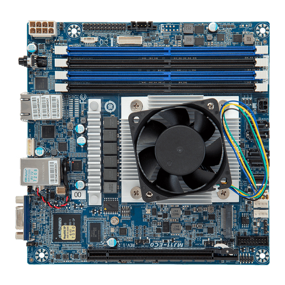
Page 5: Mj11-Ec0 Motherboard Layout
MJ11-EC0 Motherboard Layout - 5 -... - Page 6 Item Code Description VGA Port 80 Debug Port Battery Cable Connector USB3_MLAN Server Management LAN Port (Top)/ USB3.1 Ports (Bottom) IPMB IPMB Connector GbE Ethernet LAN Port #1 Support NCSI (Top)/ LAN1_2 GbE Ethernet LAN Port #2 (Bottom) SW_PWR_ID Power Button (Top)/ ID Button with LED (Bottom) P12V_AUX1 2x4 Pin 12V Power Connector SGPIO1...
-
Page 7: Block Diagram
Block Diagram - 7 -... -
Page 8: Chapter 1 Hardware Installation
Chapter 1 Hardware Installation Installation Precautions The motherboard contains numerous delicate electronic circuits and components which can become damaged as a result of electrostatic discharge (ESD). Prior to installation, carefully read the user's manual and follow these procedures: • Prior to installation, do not remove or break motherboard S/N (Serial Number) sticker or warranty sticker provided by your dealer. -
Page 9: Product Specifications
Product Specifications AMD EPYC™ 3151 SoC processor Š Single processor, 7nm, TDP 45W Š Processor Frequency: 2.7GHz-2.9GHz Š Up to 4-core, 8 threads per processor Š 2MB L2 Cache, 16MB L3 Cache Š Chipset System on Chip Š Memory 4 x DIMM slots Š... - Page 10 GIGABYTE Management Console (AMI MegaRAC SP-X) web interface Š Mini-ITX Š Form Factor 170W x 170D (mm) Š GIGABYTE reserves the right to make any changes to the product specifications and product-related information without prior notice. Hardware Installation - 10 -...
-
Page 11: Installing And Removing Memory
Installing and Removing Memory Read the following guidelines before you begin to install the memory: • Make sure that the motherboard supports the memory. It is recommended that memory of the same capacity, brand, speed, and chips be used. • Always turn off the computer and unplug the power cord from the power outlet before installing the memory to prevent hardware damage. -
Page 12: Installing And Removing A Memory Module
1-3-2 Installing and Removing a Memory Module Before installing a memory module, make sure to turn off the computer and unplug the power cord from the power outlet to prevent damage to the memory module. Be sure to install DDR4 DIMMs on to this motherboard. Follow these instructions to install a DIMM module: Insert the DIMM memory module vertically into the DIMM slot and push it down. -
Page 13: Installing And Removing The M.2 Ssd Module
Installing and Removing the M.2 SSD Module Follow the steps below to install an optional M.2 SSD module on your motherboard. Step1. Insert the M.2 SSD module into the slot. Step2. Secure it with the screw, tightening as necessary to fasten the M.2 SSD module in place. - 13 - Hardware Installation... -
Page 14: Back Panel Connectors
Back Panel Connectors Power Button Press the button to turn on/off the system. ID button with LED When the system identification is active, the ID LED on the front/ back panel glows blue. RJ-45 LAN Port #1 The Gigabit Ethernet LAN port provides Internet connection at up to 1 Gbps data rate. See the section below for a description of the states of the LAN port LEDs. -
Page 15: Internal Connectors
Internal Connectors P12V_AUX1 PMBUS DC_IN1 12) F_USB3 SATA0 13) COM1 SATA1 14) BP_1 SATA2 15) IPMB SATA3 16) FP_1 SGPIO1 17) 80H CPU0_FAN 18) BAT SYS_FAN1 10) SYS_FAN2 Read the following guidelines before connecting external devices: • First make sure your devices are compliant with the connectors you wish to connect. •... - Page 16 1/2) P12V_AUX1/DC_IN1 (2x4 12V Power Connector & 2x2 5VSB/PSON Power Connector) With the use of the power connector, the power supply can supply enough stable power to all the components on the motherboard. Before connecting the power connector, first make sure the power supply is turned off and all devices are properly installed. The power connector possesses a foolproof design. Connect the power supply cable to the power connector in the correct orientation.
- Page 17 3/4/5/6) SATA0/SATA1/SATA2/SATA3 (SATA 6Gb/s Connectors) The SATA connectors conform to SATA 6Gb/s standard and are compatible with SATA 3Gb/s standard. Each SATA connector supports a single SATA device. Pin No. Definition 7) SGPIO1 (SATA SGPIO) Connector Serial General Purpose Input/Output (SGPIO) is a communication method used between a host bus adapter (HBA) and a main board.
- Page 18 8/9/10) CPU0_FAN//SYS_FAN1/SYS_FAN2 (CPU FAN/System FAN Headers) The motherboard has one 4-pin CPU fan header (CPU_FAN), and two 4-pin (SYS_FAN) system fan headers. Most fan headers possess a foolproof insertion design. When connecting a fan cable, be sure to connect it in the correct orientation (the black connector wire is the ground wire). The motherboard supports CPU fan speed control, which requires the use of a CPU fan with fan speed control design.
- Page 19 12) F_USB3 (USB 3.1 Connector) The connector/header conform to USB 3.1 specification. Each USB connector/header can provide two USB ports via an optional USB bracket. For purchasing the optional USB bracket, please contact the local dealer. USB 3.1 Connector Pin No. Definition Pin No. Definition Power IntA_P2_D+ 20 1 IntA_P1_SSRX- IntA_P2_D- IntA_P1_SSRX+ IntA_P2_SSTX+ F_USB2 IntA_P1_SSTX- IntA_P2_SSTX-...
- Page 20 14) BP_1 (HDD Backplane Board Header) Pin No. Definition Pin No. Definition Reserved BPMI DIN/OUT BPMI DOUT/IN BPMI_LOAD BPMI_CLK PLD_Program_EN GLED_AMB_N GLED_GRN_N FAN_IRQ_N Reserved BP_SCL BP_SDA BP_RST_N SMB_U2_TMP_SCL SMB_U2_TMP_SDA I2C_DEV_RST PH_HP_SCL0 PH_HP_SDA0 P3V3_AUX P3V3_AUX 15) IPMB (Intelligent Platform Management Bus) Connector The Intelligent Platform Management Bus Communications Protocol defines a byte-level transport for transferring Intelligent Platform Management Interface Specification (IPMI) messages between intelligent I2C devices.
- Page 21 16) FP_1 (Front Panel Header) Connect the power switch, reset switch, speaker, chassis intrusion switch/sensor and system status indicator on the chassis to this header according to the pin assignments below. Note the positive and negative pins before connecting the cables. Pin No.
- Page 22 17) 80H (80 Debug Port) Pin No. Definition CLOCK LPC_FRAME LPC_LAD0 RESET LPC_LAD1 LPC_LAD3 LPC_LAD2 P3V3 LPC_IRQ 18) BAT (Battery Socket) The battery provides power to keep the values (such as BIOS configurations, date, and time information) in the CMOS when the computer is turned off. Replace the battery when the battery voltage drops to a low level, or the CMOS values may not be accurate or may be lost.
-
Page 23: Jumper Settings
Jumper Settings Clear CMOS CLR_CMOS Default Enable Jumper Name Jumper Setting 1-2: Normal operation. (Default) Clear CMOS 2-3: Clear CMOS data. - 23 - Hardware Installation... -
Page 24: Chapter 2 Bios Setup
Chapter 2 BIOS Setup BIOS (Basic Input and Output System) records hardware parameters of the system in the EFI on the motherboard. Its major functions include conducting the Power-On Self-Test (POST) during system startup, saving system parameters, loading the operating system etc. The BIOS includes a BIOS Setup program that allows the user to modify basic system configuration settings or to activate certain system features. When the power is turned off, the battery on the motherboard supplies the necessary power to the CMOS to keep the configuration values in the CMOS. - Page 25 Main This setup page includes all the items of the standard compatible BIOS. Advanced This setup page includes all the items of AMI BIOS special enhanced features. (ex: Auto detect fan and temperature status, automatically configure hard disk parameters.) Chipset This setup page includes all the submenu options for configuring the functions of the North Bridge. Server Management Server additional features enabled/disabled setup menus. ...
-
Page 26: The Main Menu
The Main Menu Once you enter the BIOS Setup program, the Main Menu (as shown below) appears on the screen. Use arrow keys to move among the items and press <Enter> to accept or enter other sub-menu. Main Menu Help The on-screen description of a highlighted setup option is displayed on the bottom line of the Main Menu. - Page 27 Parameter Description BIOS Information Project Name Displays the project name information. Project Version Displays version number of the BIOS setup utility. Build Date and Time Displays the date and time when the BIOS setup utility was created. BMC Information (Note1) BMC Firmware Version Displays BMC firmware version information. (Note1) Processor Information CPU0 Brand String/ CPU Speed / Displays the technical specifications for the installed processor(s).
- Page 28 Parameter Description AGESA PI Version PI Version Displays AGESA PI version information. Onboard LAN Information LAN1 MAC Address (Note) Displays LAN MAC address information. LAN2 MAC Address (Note) Displays LAN MAC address information. System Date Sets the date following the weekday-month-day-year format. System Time Sets the system time following the hour-minute-second format.
-
Page 29: Advanced Menu
Advanced Menu The Advanced Menu displays submenu options for configuring the function of various hardware components. Select a submenu item, then press <Enter> to access the related submenu screen. - 29 - BIOS Setup... -
Page 30: Trusted Computing
2-2-1 Trusted Computing Parameter Description TPM20 Device Found Enable/Disable BIOS support for security device. OS will not show security device. TCG EFI protocol and INT1A interface will not be Security Device Support available. Options available: Enable, Disable. Default setting is Enable. Active PCR banks Displays active Platform Configuration Register (PCR) banks. - Page 31 Enable/Disable storage hierarchy. Storage Hierarchy Options available: Enabled, Disabled. Default setting is Enabled. Enable/Disable endorsement hierarchy. Endorsement Hierarchy Options available: Enabled, Disabled. Default setting is Enabled. Selects the TCG2 spec version support. TPM2.0 UEFI Spec Version Options available: TCG_1_2, TCG_2. Default setting is TCG2. Selects the physical presence spec version.
-
Page 32: Psp Firmware Versions
2-2-2 PSP Firmware Versions The PSP Firmware Versions page displays the basic PSP firmware version information. Items on this window are non-configurable. BIOS Setup - 32 -... -
Page 33: Ast2500 Super Io Configuration
2-2-3 AST2500 Super IO Configuration Description Parameter AST2500 Super IO Configuration Super IO Chip Displays the super IO chip information Serial Port 1 Configuration Press [Enter] for configuration of advanced items. - 33 - BIOS Setup... - Page 34 2-2-3-1 Serial Port 1 Configuration Description Parameter Serial Port 1/2 Configuration Enable/Disable the Serial Port (COM). When set to Enabled allows you to configure the Serial port 1 settings. When set to Disabled, displays no Serial Port (Note1) configuration for the serial port. Options available: Enabled, Disabled. Default setting is Enabled. Devices Settings Displays the Serial Port 1 device settings. (Note2) Select an optimal settings for Super IO Device.
-
Page 35: S5 Rtc Wake Settings
2-2-4 S5 RTC Wake Settings Parameter Description Enable/Disable system wake on alarm event. Options available: Disabled, Fixed Time, Dynamic Time. When Fixed Time is Wake System from S5 (Note) selected, system will wake on the hr::min::sec specified. Default setting is Disabled. (Note) Advanced items prompt when this item is defined. - 35 - BIOS Setup... -
Page 36: Serial Port Console Redirection
2-2-5 Serial Port Console Redirection Parameter Description Select whether to enable console redirection for specified device. Console COM0/Serial Over LAN redirection enables the users to manage the system from a remote Console Redirection location. (Note) Options available: Enabled, Disabled. Default setting is Disabled. Press [Enter] to configure advanced items. Please note that this item is configurable when COM0/Serial Over LAN Console Redirection is set to Enabled. - Page 37 Parameter Description Parity Š – A parity bit can be sent with the data bits to detect some transmission errors. – Even: parity bit is 0 if the num of 1's in the data bits is even. – Odd: parity bit is 0 if num of 1's in the data bits is odd. –...
- Page 38 Parameter Description Serial Port for Out-of-Band Management / Windows EMS console redirection allows the user to configure Console Redirection Emergency Management Settings to support Out-of-Band Serial Port management. Services (EMS) Console Options available: Enabled, Disabled. Default setting is Disabled. Redirection (Note) Press [Enter] to configure advanced items. Please note that this item is configurable when Serial Port for Out-of- Band Management EMS Console Redirection is set to Enabled.
-
Page 39: Cpu Configuration
2-2-6 CPU Configuration Description Parameter Enable/Disable the CPU Virtualization. SVM Mode Options available: Enabled, Disabled. Default setting is Enabled. Controls the Secure Memory Encryption Enable (SMEE) function. SMEE Options available: Enabled, Disabled. Default setting is Enabled. Press [Enter] to view the memory information related to Node 0. Node 0 Information - 39 - BIOS Setup... -
Page 40: Pci Subsystem Settings
2-2-7 PCI Subsystem Settings Description Parameter Displays the PCI Bus Driver version information. PCI Bus Driver Version Change the SL_SAS function. SL_SAS Control Options available: Disabled, SATA, PCIe x4. Default setting is PCIe x4. Change the PCIe lanes. PCIE_1 Lanes Configuration Options available: Disabled, Auto, x16, x8x8, x8x4x4, x4x4x8, x4x4x4x4. - Page 41 Description Parameter If the system has SR-IOV capable PCIe devices, this item Enable/ Disable Single Root IO Virtualization Support. SR-IOV Support Options available: Enabled, Disabled. Default setting is Disabled. Enable/Disable the PCI-E AER (Advanced Error Reporting) function. PCI-E AER Enabled Options available: Enabled, Disabled.
-
Page 42: Usb Configuration
2-2-8 USB Configuration Parameter Description USB Configuration USB Module Version Displays the USB module version information. USB Controllers Displays the supported USB controllers. USB Devices: Displays the USB devices connected to the system. Enable/Disable the Legacy USB support function. AUTO option disables legacy support if no USB devices are connected. - Page 43 Parameter Description Enables the I/O port 60h/64h emulation support. This should be enabled for the complete USB Keyboard Legacy support for non- Port 60/64 Emulation USB aware OS. Options available: Enabled, Disabled. Default setting is Enabled. USB hardware delays and time-outs Selects the time-out value for USB Control/Bulk/Interrupt transfers.
-
Page 44: Nvme Configuration
2-2-9 NVMe Configuration Parameter Description NVMe Configuration Displays the NVMe devices connected to the system. BIOS Setup - 44 -... -
Page 45: Sata Configuration
2-2-10 SATA Configuration Parameter Description Displays the installed HDD devices information. System will automatically SATA Configuration detect HDD type. - 45 - BIOS Setup... -
Page 46: Amd Cbs
2-2-11 AMD CBS Parameter Description AMD CBS Zen Common Options Press [Enter] for configuration of advanced items. DF Common Options Press [Enter] for configuration of advanced items. UMC Common Options Press [Enter] for configuration of advanced items. NBIO Common Options Press [Enter] for configuration of advanced items. FCH Common Options Press [Enter] for configuration of advanced items. NTB Common Options Press [Enter] for configuration of advanced items. BIOS Setup - 46 -... - Page 47 2-2-11-1 Zen Common Options Parameter Description Zen Common Options From a workaround for GCC/C000005 issue for XV Core on CZ A0, setting MSRC001_1029 Decode Configuration (DE_CFG) bit 14 RedirectForReturnDis [DecfgNoRdrctForReturns] to 1. Options available: Auto , 1, 0. Default setting is Auto. 0 - L2 TLB ways [11:8] are fully associative. L2 TLB Associativity 1 - L2 TLB ways [11:8] are 4K-only Options available: 0, 1, Auto.
- Page 48 Parameter Description Allows you to disagree or agree enabling processor cores and threads. When agreed, you can control the number of cores to be used, and whether to enable or disable Symmetric Multithreading Technology (SMT) support. Downcore Control Š – Options available: Auto, ONE(1+0), TWO(1+1), TWO(2+0), Core/Thread Enablement THREE(3+0), FOUR(2+2), FOUR(4+0), SIX(3+3).
- Page 49 2-2-11-2 DF Common Options Parameter Description DF Common Options Provide a value that is the number of hours to scrub memory. DRAM scrub time Options available: Auto, Disabled, 1 hour, 4 hours, 8 hours, 16 hours, 24 hours, 48 hours. Default setting is Auto. Enable/Disable the Redirect scrubber control feature.
- Page 50 Parameter Description Controls the fabric level memory interleaving. Note that channel, die, and socket has requirements on memory populations and it will be ignored if the Memory interleaving memory doesn't support the selected option. Options available: Auto, None, Channel, Die Socket. Default setting is Auto. Controls the memory interleaving size.
- Page 51 2-2-11-3 UMC Common Options Parameter Description UMC Common Options DDR4 Common Options Press [Enter] for configuration of advanced items. DRAM Memory Mapping Press [Enter] for configuration of advanced items. Memory MBIST Press [Enter] for configuration of advanced items. - 51 - BIOS Setup...
- Page 52 2-2-11-3-1 DDR4 Common Options Parameter Description DDR4 Common Options Press [Enter] to enable / disable restrictions for DDR4 frequency and voltage programming. Memory speeds will be capped at AMD guidelines. I Decline Š DRAM Timing Configuration I Accept Š – Overclock: Enable/Disable Memory Overclock Settings. –...
- Page 53 Parameter Description Press [Enter] for configuration of advanced items. Data Bus Configuration User Controls Š Data Bus Configuration – Specifies the mode for drive strength to Auto or Manual. – Options available: Auto, Manual. Default setting is Auto. Press [Enter] for configuration of advanced items. Data Poisoning Š – Enable/Disable the Data Poisoning function. – Options available: Auto, Enabled, Disabled. Default setting is Auto. RCD Parity Š –...
- Page 54 2-2-11-3-2 DRAM Memory Mapping Parameter Description DRAM Memory Mapping Interleave memory blocks across the DRAM chip selects for node 0. Chipselect Interleaving Options available: Auto, Disabled. Default setting is Auto. Configures the BankGroupSwap. BankGroupSwap (BGS) is a new memory mapping option in AGESA that alters how applications get assigned to BankGroupSwap physical locations within the memory modules.
- Page 55 2-2-11-3-3 Memory MBIST Parameter Description Memory MBIST Enable/Disable the Memory MBIST function. MBIST Enable Options available: Enabled, Disabled. Default setting is Disabled. Selects MBIST Test Mode. Options available: Interface Mode, Data Eye Mode. Default setting is Interface Mode. MBIST Test Mode (Note) –...
- Page 56 2-2-11-4 NBIO Common Options Parameter Description NBIO Common Options Press [Enter] for configuration of advanced items. IOMMU Š – Enable/Disable the IOMMU function. NB Configuration – Options available: Auto, Enabled, Disabled. Default setting is Auto. Concurrent Training Š – Enable/Disable Concurrent Training. – Options available: Auto, False, True. Default setting is Auto. NBIO Internal Poison Enable/Disable NBIO Internal Poison Consumption.
- Page 57 Parameter Description Enable/Disable PSI. Options available: Auto, Disable. Default setting is Auto. Enable/Disable ACS support. ACS Enable Options available: Auto, Enable, Disabled. Default setting is Auto. Enable/Disable Alternative Routing-ID Interpretation. PCIe ARI Support Options available: Auto, Enable, Disable. Default setting is Auto. Options available: Auto, Manual.
- Page 58 2-2-11-5 FCH Common Options Parameter Description FCH Common Options Press [Enter] for configuration of advanced items. SATA Controller Š – Enable/Disable OnChip SATA controller. – Options available: Auto, Enabled, Disabled. Default setting is Auto. Sata RAS Support Š – Enable/Disable Sata RAS Support. – Options available: Auto, Enabled, Disabled. Default setting is Auto. SATA Configuration Options Sata Disabled AHCI Prefetch Function Š...
- Page 59 Parameter Description – XHCI2 enable (MCM1/Die0) » Options available: Auto, Enabled, Disabled. Default setting is USB Configuration Options Auto. (continued) – XHCI3 enable (MCM1/Die1) » Options available: Auto, Enabled, Disabled. Default setting is Auto. Press [Enter] for configuration of advanced items. SD Configuration Mode Š SD (Secure Digital) Options – Selects the SD mode. –...
- Page 60 Parameter Description Press [Enter] for configuration of advanced items. eMMC/SD Configure Š – Options available: Disabled, SD Normal Speed, SD High Speed, SD UHSI-SDR50, SD UHSI-DDR50, SD UHSI-SDR104, eMMC Emmc Backward Compatibility, eMMC High Speed SDR, eMMC High Speed DDR, eMMC HS200, eMMC HS400, eMMC HS300, Auto. Default setting is Auto. eMMC Options Driver Type Š...
- Page 61 2-2-11-6 NTB Common Options Parameter Description NTB Common Options NTB Enable Options available: Auto, Enable. Default setting is Auto. Options available: Auto, Socket0-Die0, Socket0-Die1, Socket0-Die2, NTB Location (Note) Socket0-Die3, Socket1-Die0, Socket1-Die1, Socket1-Die2, Socket1-Die3. Default setting is Auto. NTB enable on PCIe Core. NTB active on PCIeCore (Note) Options available: Auto, Core0, Core1.
-
Page 62: Network Stack Configuration
2-2-12 Network Stack Configuration Parameter Description Enable/Disable the UEFI network stack. Network Stack Options available: Enabled, Disabled. Default setting is Enabled. Enable/Disable the Ipv4 PXE feature. Ipv4 PXE Support (Note) Options available: Enabled, Disabled. Default setting is Enabled. Enable/Disable the Ipv4 HTTP feature. Ipv4 HTTP Support (Note) Options available: Enabled, Disabled. -
Page 63: Iscsi Configuration
2-2-13 iSCSI Configuration Parameter Description Press [Enter] and name iSCSI Initiator. Only IQN format is accepted. iSCSI Initiator Name Range: from 4 to 223 Add an Attempt Press [Enter] to configure advanced items. Delete Attempts Press [Enter] to configure advanced items. Change Attempt Order Press [Enter] to configure advanced items. - 63 - BIOS Setup... -
Page 64: T1S Auth Configuration
2-2-14 T1s Auth Configuration Parameter Description Press [Enter] for configuration of advanced items. Enroll Cert Š – Press [Enter] to enroll a certificate • Enroll Cert Using File • Cert GUID Server CA Configuration Input digit character in 1111111-2222-3333-4444-1234567890ab format. – Commit Changes and Exit – Discard Changes and Exit Delete Cert Š Press [Enter] for configuration of advanced items. Client Cert Configuration BIOS Setup - 64 -... -
Page 65: Intel(R) I210 Gigabit Network Connection
2-2-15 Intel(R) I210 Gigabit Network Connection - 65 - BIOS Setup... - Page 66 Parameter Description Press [Enter] to configure advanced items. Link Speed Š – Allows for automatic link speed adjustment. – Options available: Auto Negotiated, 10 Mbps Half, 10 Mbps Full, 100 Mbps Half, 100 Mbps Full. Default setting is Auto Negotiated. NIC Configuration Wake On LAN Š – Enables power on of the system via LAN. Note that configuring Wake on LAN in the operating system does not change the value of this setting, but does override the behavior of Wake on LAN in OS controlled power states.
-
Page 67: Vlan Configuration
2-2-16 VLAN Configuration - 67 - BIOS Setup... - Page 68 Parameter Description Press [Enter] to configure advanced items. Create new VLAN Š VLAN ID Š – Sets VLAN ID for a new VLAN or an existing VLAN. – Press the <+> / <-> keys to increase or decrease the desired values. – The valid range is from 0 to 4094. Priority Š...
-
Page 69: Mac Ipv4 Network Configuration
2-2-17 MAC IPv4 Network Configuration Parameter Description Indicates whether network address is configured successfully or not. Configured Options available: Enabled, Disabled. Default setting is Disabled. Options available: Enabled, Disabled. Default setting is Enabled. Enable DHCP (Note) Local IP Address Press [Enter] to configure local IP address. (Note) Press [Enter] to configure local NetMask. Local NetMask (Note) Press [Enter] to configure local Gateway Local Gateway (Note) Press [Enter] to configure local DNS servers Local DNS Servers... -
Page 70: Mac Ipv6 Network Configuration
2-2-18 MAC IPv6 Network Configuration BIOS Setup - 70 -... - Page 71 Parameter Description Press [Enter] to configure advanced items. Displays the MAC Address information. Š Interface ID Š – The 64 bit alternative interface ID for the device. The string is colon separated. e.g. ff:dd:88:66:cc:1:2:3. DAD Transmit Count Š – The number of consecutive Neighbor solicitation messages sent Enter Configuration Menu while performing Duplicate Address Detection on a tentative address.
-
Page 72: Chipset Setup Menu
Chipset Setup Menu Chipset Setup menu displays submenu options for configuring the function of the North Bridge. Select a submenu item, then press <Enter> to access the related submenu screen. Parameter Description Simultaneous multithreading. Off=1T single-thread; Auto=2T two-thread if SMT Mode capable. Options available: Off, Auto. Default setting is Auto. Configures the PCIe Link training in 1 or 2 steps. PCIe Link Training Type Options available: 1 Step, 2 Step. -
Page 73: North Bridge
2-3-1 North Bridge Parameter Description North Bridge Configuration Memory Information Total Memory Displays the total memory information. Socket 0 Information Press [Enter] to view information related to Socket 0. - 73 - BIOS Setup... -
Page 74: Error Management
2-3-2 Error Management Parameter Description Error Management Options available: Enabled, Disabled. Default setting is Enabled. Platform First Error Handling Specifies the MCA Error Threshold Count. MCA Error Threshold Count Options available: 0, 1, 5, 10, 100, 1000. Default setting is 10. DRAM Address/Command Parity with Replay RCD Parity Options available: Enabled, Disabled. -
Page 75: Server Management Menu
Server Management Menu Parameter Description Enable/Disable FRB-2 timer (POST timer). FRB-2 Timer Options available: Enabled, Disabled. Default setting is Enabled. Configures the FRB2 Timer timeout. FRB-2 Timer Options available: 3 minutes, 4 minutes, 5 minutes, 6 minutes. Default setting is 6 timeout minutes. Please note that this item is configurable when FRB-2 Timer is set to Enabled. Configures the FRB2 Timer policy. - Page 76 Parameter Description Configures time to wait BMC ready. Wait BMC Ready Options available: Disabled, 2 minutes, 4 minutes, 6 minutes. Default setting is 10 minutes. System Event Log Press [Enter] to configure advanced items. View FRU Press [Enter] to view the FRU information. Information BMC network Press [Enter] to configure advanced items. configuration IPv6 BMC Network Press [Enter] to configure advanced items.
-
Page 77: System Event Log
2-4-1 System Event Log Parameter Description Enabling / Disabling Options Change this item to enable or disable all features of System Event SEL Components Logging during boot. Options available: Enabled, Disabled. Default setting is Enabled. Erasing Settings Choose options for erasing SEL. Erase SEL Options available: No/Yes, On next reset/Yes, On every reset. -
Page 78: View Fru Information
2-4-2 View FRU Information The FRU page is a simple display page for basic system ID information, as well as System product information. Items on this window are non-configurable. (Note) The model name will vary depends on the product you purchased BIOS Setup - 78 -... -
Page 79: Bmc Network Configuration
2-4-3 BMC Network Configuration Parameter Description BMC network configuration Lan Channel 1 Selects to configure LAN channel parameters statically or dynamically (DHCP). Do nothing option will not modify any BMC network parameters Configuration Address source during BIOS phase. Options available: Unspecified, Static, DynamicBmcDhcp. Default setting is DynamicBmcDhcp. Station IP address Displays IP Address information. Displays Subnet Mask information. Subnet mask Please note that the IP address must be in three digitals, for example, 192.168.000.001. -
Page 80: Ipv6 Bmc Network Configuration
2-4-4 IPv6 BMC Network Configuration Parameter Description IPv6 BMC network configuration IPv6 BMC Lan Channel 1 Enable/Disable IPv6 BMC LAN channel function. When this item is disabled, the system will not modify any BMC network during BIOS IPv6 BMC Lan Option phase. Options available: Unspecified, Disable, Enable. Default setting is Enable. -
Page 81: Security Menu
Security Menu The Security menu allows you to safeguard and protect the system from unauthorized use by setting up access passwords. There are two types of passwords that you can set: • Administrator Password Entering this password will allow the user to access and change all settings in the Setup Utility. •... -
Page 82: Secure Boot
2-5-1 Secure Boot The Secure Boot submenu is applicable when your device is installed the Windows 8 (or above) operating ® system. Parameter Description System Mode Displays if the system is in User mode or Setup mode. Enable/ Disable the Secure Boot function. Secure Boot Options available: Enabled, Disabled. - Page 83 Parameter Description Press [Enter] to configure advanced items. Please note that this item is configurable when Secure Boot Mode is set to Custom. Factory Key Provision Š – Allows to provision factory default Secure Boot keys when system is in Setup Mode. – Options available: Enabled, Disabled. Default setting is Disabled. Restore Factory Keys Š...
- Page 84 Parameter Description Authorized TimeStamps (DBT) Š – Displays the current status of the Authorized TimeStamps Database. – Press [Enter] to configure a new DBT or load additional DBT from storage devices. Key Management – Options available: Update, Append. (continued) OsRecovery Signatures Š – Displays the current status of the OsRecovery Signature Database. –...
-
Page 85: Boot Menu
Boot Menu The Boot menu allows you to set the drive priority during system boot-up. BIOS setup will display an error message if the legacy drive(s) specified is not bootable. Parameter Description Boot Configuration Number of seconds to wait for setup activation key. 65535 (0xFFFF) Setup Prompt Timeout means indefinite waiting. Press the numeric keys to input the desired values. - Page 86 Parameter Description UEFI USB Drive BBS Priorities Press [Enter] to configure the boot priority. UEFI Network Drive BBS Press [Enter] to configure the boot priority. Priorities UEFI Application Boot Priorities Press [Enter] to configure the boot priority. BIOS Setup - 86 -...
-
Page 87: Save & Exit Menu
Save & Exit Menu The Save & Exit menu displays the various options to quit from the BIOS setup. Highlight any of the exit options then press <Enter>. Parameter Description Save Options Saves changes made and closes the BIOS setup. Save Changes and Exit Options available: Yes, No. -
Page 88: Abl Post Codes
ABL POST Codes 2-8-1 StartProcessorTestPoints Entry used for range testing for @b Processor related TPs 0xE000 2-8-2 Memory test points Memory structure initialization (Public interface) 0xE001 SPD Data processing (Public interface) 0xE002 Memory configuration (Public interface) Phase 1 0xE003 DRAM initialization 0xE004 ProcMemSPDChecking 0xE005 ProcMemModeChecking 0xE006 Speed and TCL configuration 0xE007... -
Page 89: Original Post Code
ABL Mem - PMU Stage Training Wr 2D 0xE023 ABL Mem - PMU Queue Empty 0xE024 ABL Mem - PMU US message Start 0xE025 ABL Mem - PMU US message End 0xE026 ABL Mem - PMU Complete 0xE027 ABL Mem - PMU - After PMU Training 0xE028 ABL Mem - PMU - Before Disable PMU 0xE029... -
Page 90: Cpu Test Points
ABL Mem - Before OtherTiming 0xE04A ABL Mem - Before UMAMemTyping 0xE04B ABL Mem - Before SetDqsEccTmgs 0xE04C ABL Mem - Before MemClr 0xE04D ABL Mem - Before On DIMM Thermal 0xE04E ABL Mem - Before DMI 0xE04F ABL MEM - End of phase 3 memory code 0xE050 2-8-5 CPU test points Entry point CPU init after training... -
Page 91: Gnb Earlier Init
2-8-8 Gnb Earlier init TP0x90 0xE090 GNB earlier interface 0xE091 GNB internal debug code 0xE092 GNB internal debug code 0xE093 GNB internal debug code 0xE094 GNB internal debug code 0xE095 GNB internal debug code 0xE096 GNB internal debug code 0xE097 GNB internal debug code 0xE098 GNB internal debug code... - Page 92 ABL 2 Begin 0xE0B8 ABL 2 Initialization 0xE0B9 ABL 2 After Training 0xE0BA ABL 2 Debug Synchronization 0xE0BB ABL 2 Error detected 0xE0BC ABL 2 Global memory error detected 0xE0BD ABL 2 End 0xE0BE ABL 3 Begin 0xE0BF ABL 3 Initialziation 0xE0C0 ABL 3 GMI/xGMI Initialization Stage 1 0xB1C0...
- Page 93 ABL 4 APOB Initialzation - cold boot 0xE0CA ABL 4 Finalize memory settings - cold boot 0xE0CB ABL 4 CPU Initialize Optimized Boot - cold boot 0xE0CC ABL 4 Gmi Pcie Training - cold boot 0xE0CD ABL 4 Cold boot End 0xE0CE ABL 4 Initialization - Resume boot 0xE0CF...
-
Page 94: Pmu Test Points
Before the memory code calls out to locate a buffer 0xE0F3 After the memory code calls out to locate a buffer 0xE0F4 Before the memory code calls out to locate a buffer 0xE0F5 After the memory code calls out to locate a buffer 0xE0F6 Before the memory code calls out to locate a buffer 0xE0F7... - Page 95 ABL Error for Soc Scan No Die error 0xE2AC ABL Error for Nb Tech Heap Aloc error 0xE2AD ABL Error for No Nb Constructor error 0xE2AE ABL Error for No Tech Constructor error 0xE2AE ABL Error for ABL1b Auto Alocation error 0xE2B0 ABL Error for ABL1b No NB Constructor error 0xE2B1...
- Page 96 ABL Error over clock Mem Init Error 0xE2D5 ABL Error over clock Mem Other Error 0xE2D6 ABL Error for ABL6 General Error 0xE2D7 ABL Error Event Log Error 0xE2D8 ABL Error FATAL ABL1 Log Error 0xE2D9 ABL Error FATAL ABL2 Log Error 0xE2DA ABL Error FATAL ABL3 Log Error 0xE2DB...
- Page 97 ABL Error ABL 2 Mem Init Error 0xE302 ABL Error ABL 4 Mem Init Error 0xE303 ABL Error ABL 6 Mem Init Error 0xE304 ABL Error ABL 1 error repor Error 0xE305 ABL Error ABL 2 error repor Error 0xE306 ABL Error ABL 3 error repor Error 0xE307 ABL Error ABL 4 error repor Error...
-
Page 98: Agesa Post Codes
Agesa POST Codes 2-9-1 Universal Post Code Universal ACPI entry 0xA001 Universal ACPI exit 0xA002 Universal ACPI abort 0xA003 Universal SMBIOS entry 0xA004 Universal SMBIOS exit 0xA005 Universal SMBIOS abort 0xA006 2-9-2 [0xA1XX] For CZ only memory Postcodes Memory structure initialization (Public interface) 0xA101 SPD Data processing (Public interface) 0xA102... - Page 99 Calculate MaxRdLatency per channel 0xA120 TpProcMemReceiveDqsTraining 0xA121 Set Write Data delay 0xA122 Write test pattern 0xA123 Start read sweep 0xA124 Set Receive DQS delay 0xA125 Read Test pattern 0xA126 Compare Test pattern 0xA127 Update results 0xA128 Start Find passing window 0xA129 TpProcMemTransmitDqsTraining 0xA12A...
- Page 100 Before InitMCT 0xA149 Before OtherTiming 0xA14A Before UMAMemTyping 0xA14B Before SetDqsEccTmgs 0xA14C Before MemClr 0xA14D Before On DIMM Thermal 0xA14E Before DMI 0xA14F End of memory code 0xA150 Entry point S3Init 0xA151 Sending MRS2 0xA180 Sedding MRS3 0xA181 Sending MRS1 0xA182 Sending MRS0 0xA183...
-
Page 101: S3 Interface Post Code
BR Init Mid end 0xA19E BR Init Late entry 0xA19F BR Init Late install protocol 0xA1A0 BR Init Late end 0xA1A1 BR DXE install complete protocol 0xA1A2 UNB install complete PPI 0xA1A3 UNB AfterApLaunch callback entry 0xA1A4 UNB AfterApLaunch callback end 0xA1A5 2-9-3 S3 Interface Post Code Before the S3 save code calls out to allocate a buffer... - Page 102 PspSmmV1 SwSmiCallBack exit, build the S3 save area for resume 0xA511 PspSmmV1 BspSmmResumeVector entry 0xA512 PspSmmV1 BspSmmResumeVector exit 0xA513 PspSmmV1 ApSmmResumeVector entry 0xA514 PspSmmV1 ApSmmResumeVector exit 0xA515 PspP2CmboxV1 entry 0xA516 PspP2CmboxV1 exit 0xA517 // PSP V2 Modules PspPeiV2 entry 0xA521 PspPeiV2 exit 0xA522 PspDxeV2 entry...
- Page 103 PspP2Cmbox Command SpiSetAttrib Handling entry 0xA592 PspP2Cmbox Command SpiGetBlockSize Handling entry 0xA593 PspP2Cmbox Command SpiReadFV Handling entry 0xA594 PspP2Cmbox Command SpiWriteFV Handling entry 0xA595 PspP2Cmbox Command SpiEraseFV Handling entry 0xA596 PspP2Cmbox Command Handling exit 0xA59E PspP2Cmbox Command Handling Fail exit 0xA59F // C2P mailbox Handling PSP C2P mailbox entry base [0xA5BX | Cmd]...
-
Page 104: 0Xa9Xx, 0Xaaxx] Assigned For Agesa Nbio Module
2-9-6 [0xA9XX, 0xAAXX] assigned for AGESA NBIO Module // NbioBase AmdNbioBase PEIM driver entry 0xA900 AmdNbioBase PEIM driver exit 0xA901 AmdNbioBase DXE driver entry 0xA902 AmdNbioBase DXE driver exit 0xA903 // PCIe AmdNbioPcie PEIM driver entry 0xA904 AmdNbioPcie PEIM driver exit 0xA905 AmdNbioPcie DXE driver entry 0xA906... - Page 105 // APCB SMM APCB SMM Entry 0xA924 APCB SMM Exit 0xA925 // [0xA950, 0xA99F] NBIO PPI/PROTOCOL Callback NbioTopologyConfigureCallback entry 0xA950 NbioTopologyConfigureCallback exit 0xA951 MemoryConfigDoneCallbackPpi entry 0xA952 MemoryConfigDoneCallbackPpi exit 0xA953 DxioInitializationCallbackPpi entry 0xA954 DxioInitializationCallbackPpi exit 0xA955 DispatchSmuV9Callback entry 0xA956 DispatchSmuV9Callback exit 0xA957 DispatchSmuV10Callback entry 0xA958 DispatchSmuV10Callback exit 0xA959 AmdPcieMiscInit Event entry...
-
Page 106: 0Xacxx] Assigned For Agesa Ccx Module
GfxConfigEnvInterface entry 0xA984 GfxConfigEnvInterface exit 0xA985 GfxEnvInterfaceCZ entry 0xA986 GfxEnvInterfaceCZ exit 0xA987 GfxMidInterfaceCZ entry 0xA988 GfxMidInterfaceCZ exit 0xA989 GfxIntInfoTableInterfaceCZ entry 0xA98A GfxIntInfoTableInterfaceCZ exit 0xA98B PcieMidInterfaceCZ entry 0xA98C PcieMidInterfaceCZ exit 0xA98D GnbMidInterfaceCZ entry 0xA98E GnbMidInterfaceCZ exit 0xA98F GnbSmuMidInterfaceCZ entry 0xA990 GnbSmuMidInterfaceCZ exit 0xA991 InvokeAmdInitLate entry 0xA992 InvokeAmdInitLate exit... -
Page 107: 0Xadxx] Assigned For Agesa Df Module
2-9-8 [0xADXX] assigned for AGESA DF Module DF PEI entry 0xAD50 DF DXE entry 0xAD55 DF Ready to Boot entry 0xAD56 DF PEI exit 0xADE0 DF DXE exit 0xADE5 DF Ready to Boot exit 0xADE6 2-9-9 [0xAFXX] assigned for AGESA FCH Module FCH InitReset dispatch point 0xAF01 FCH InitEnv dispatch point... - Page 108 FCH InitEnv AB Link 0xAF51 FCH InitEnv LPC 0xAF52 FCH InitEnv SPI 0xAF53 FCH InitEnv eSPI 0xAF54 FCH InitEnv SD 0xAF55 FCH InitEnv eMMC 0xAF56 FCH InitEnv SATA 0xAF57 FCH InitEnv USB 0xAF58 FCH InitEnv xGbE 0xAF59 FCH InitEnv HwAcpiP 0xAF5F FCH InitMid HwAcpi 0xAF60...
-
Page 109: Bios Post Beep Code (Ami Standard)
2-10 BIOS POST Beep code (AMI standard) 2-10-1 PEI Beep Codes # of Beeps Description Memory not Installed. Memory was installed twice (InstallPeiMemory routine in PEI Core called twice) Recovery started DXEIPL was not found DXE Core Firmware Volume was not found Recovery failed S3 Resume failed Reset PPI is not available...
Need help?
Do you have a question about the MJ11-EC0 and is the answer not in the manual?
Questions and answers