
Related Manuals for Shuttle HOT-617


Summary of Contents for Shuttle HOT-617
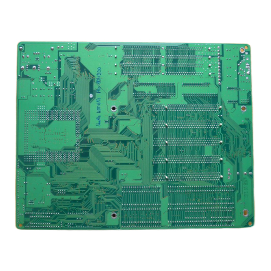
- Page 1 HOT-617 Pentium Pro processor ™ Based PCI MAIN BOARD User's Manual User's Manual 1...
- Page 2 CE Notice: Following standards were applied to this product, in order to achieve compliance with the electromagnetic compatibility: - Immunity in accordance with EN 50082-1: 1992 - Emmitions in accordance with EN 55022: 1987 Class B. FCC Notice: This equipment has been tested and found to comply with the limits for a Class B digital device, pursuant to Part 15 of FCC Rules.
-
Page 3: Table Of Contents
ABLE OF ONTENTS ..................4 REFACE ............. 5 HAPTER NTRODUCTION Specification......................... 5 ........... 7 HAPTER ARDWARE ONFIGURATION Jumpers..........................7 CPU Clock Speed Selection....................8 Onboard Voltage Regulators....................9 Onboard Voltage Regulatro VIO Output - JP9, JP10 ............9 Clear CMOS - JP8....................... 9 Flash EEPROM Jumper - JP1 ................... -
Page 4: Preface
Preface HOT-617 mainboard is a highly integrated IBM PC/AT compatible system board. The design will accept Intel Pentium Pro processors with size of 256KB and 512KB cache. The memory subsystem is designed to support up to 512 MB of EDO, Burst EDO, and Fast Page Mode DRAM Module in standard 72-pin SIMM socket. -
Page 5: Chapter 1 Introduction
Chapter Specification Supports 180MHz or 200MHz Pentium™ Pro CPU on a ZIF socket 8. Note : HOT-617 main board doesn't support older Pentium ™ Pro processors without VID(Voltage Identification) supported Chipset Features Intel's i440FX PCIset with ITE Giga I/O subsystems. - Page 6 Expansions 32-bit PCI bus slot x 5 16-bit ISA bus slot x 3 2-channel PCI IDE port support up to 4 IDE devices. - PIO Mode 4, DMA Mode 2 transfers up to 22 MB/sec - Integrated 8 x 32-bit buffer for PCI IDE burst transfers One floppy port One parallel port - Supports SPP (PS/2 compatible bidirectional Parallel Port),...
-
Page 7: Chapter 2 Hardware Configuration
Hardware Configuration Chapter Jumpers User's Manual 7... -
Page 8: Cpu Clock Speed Selection
MHz to 66 MHz and PCI Bus Clock from 25MHz to 33MHz. HOT-617 mainboard also provides Jumper JP4 to figure the CPU Core Clock multiplier. By inserting or removing jumper caps on JP4, the user can change the System Bus Clock/CPU Core Clock ratio from 1 : 2 to 1 : 4. -
Page 9: Onboard Voltage Regulators
VID supported . Onboard Voltage Regulator V Output- JP9, JP10 HOT-617 mainboard is designed an additional feature to adjust V voltage which provide power to CPU and chipsets. voltages adjustable from 3.1V to 3.8 V by jumpers JP9 and JP10. Normally, V adjust by the user is not required. -
Page 10: Flash Eeprom Jumper - Jp1
Flash EEPROM Jumper - JP1 HOT-617 mainboard supports two types of flash EEPROM, 5 volt and 12 volt. By setting up jumper JP1, you can update both types of flash EEPROM with new system BIOS files as they come available. -
Page 11: Connectors & Sockets
Connectors & Sockets Connectors ITEM FUNCTION IDEP1 On-board PCI Primary IDE Connector IDES1 On-board PCI Secondary IDE Connector FLOPPY On-board Floppy Controller Connector PRINTER On-board Parallel Port Connector COMP1 On-board Serial port-1 Connector On-board Serial Port-2 Connector COMS1 IrDA Connector - * Note 1 J1, J2 USB Connectors - * Note 2 ATKB1... -
Page 12: Chapter 3 Memory Configuration
Memory Configuration Chapter The HOT-617 mainboard provides four 72-pin SIMM(Single In-line Memory Module) sockets that make it possible to install up to 512MB of RAM. The SIMM socket support 4MB, 8MB, 16MB, 32MB, 64MB, and 128MB Fast Page Mode(FPM), EDO(Extended Data Output), and Burst EDO(BEDO). -
Page 13: Chapter 4 Award Bios Setup
Award BIOS Setup Chapter HOT-617 BIOS ROM has a built-in Setup program that allows users to modify the basic system configuration. This type of information is stored in battery-backed RAM so that it retains the Setup information when the power is turned off. -
Page 14: The Main Menu
The Main Menu Standard CMOS setup This setup page includes all the items in a standard compatible BIOS. BIOS features setup This setup page includes all the items of Award special enhanced features. Chipset features setup This setup page includes all the items of chipset features. Power Management Setup This setup page includes all the items of Power Management features. - Page 15 Integrated Peripherals This setup page includes all the items of peripheral features. IDE HDD auto detection Automatically configure IDE hard disk drive parameters. Supervisor Password Change, set, or disable supervisor password. It allows you to limit access to the system and Setup, or just to Setup.
-
Page 16: Standard Cmos Setup
Standard CMOS Setup Date The date format is <day>, <month> <date> <year>. Press <F3> to show the calendar. Time The time format is <hour> <minute> <second>. The time is calculated base on the 24- hour military-time clock. For example. 5 p.m. is 17:00:00. Drive C type/Drive D type The categories identify the types of 2 channels that have been installed in the computer. - Page 17 Drive A type/Drive B type This item specifies the types of floppy disk drive A or drive B that has been installed in the system. Video This item selects the type of adapter used for the primary system monitor that must matches your video display card and monitor.
-
Page 18: Bios Features Setup
BIOS Features Setup CPU Internal Cache This item enables CPU internal cache to speed up memory access. External Cache This item enables the external cache to speed up memory access. Quick Power On Self Test This item speeds up Power On Self Test (POST) after you power on the computer. If it is set to Enabled, BIOS will shorten or skip some check items during POST. - Page 19 Boot Up System Speed This option sets the speed of the CPU at system boot time. The settings are High or Low. Gate A20 Option When this item sets to Normal, the A20 signal is controlled by keyboard controller. When this item sets to Fast, the A20 signal is controlled by post 92 or chipset specific method.
-
Page 20: Chipset Features Setup
Chipset Features Setup The Chipset Features Setup option is used to control the configuration of chipset registers value. The registers may affect the system stability, please do not change these settings if you are not familiar with the chipset. Auto Configuration This item auto configure the following items: DRAM RAS# Precharge time, MA Additional Wait State, RAS# to CAS# Delay, DRAM Read Burst, DRAM Write Burst, and ISA Bus Clock by different system clock. - Page 21 MA Additional Wait State When enabled, one additional wait state is inserted before the assertion of the first memory address line MA and CAS/RAS assertion during DRAM read or write leadoff cycles. RAS To CAS# Delay When DRAM is refreshed, both rows and columns are address separately. This setup item allows you to determine the timing of the transition from Row Address Strobe (RAS) to Column Address Strobe (CAS).
- Page 22 PCI Burst Write Combining When enabled will increase the efficiency of PCI bus by combining serval CPU to PCI write cycles into one. PCI-To-DRAM Pipeline When enabled will increase the bandwidth of the path between the PCI and the DRAM to enhance the PCI bus efficiency and DRAM accessing CPU-To-PCI Write Post When enabled will increase the efficiency of the PCI bus and speed up the execution in the...
- Page 23 Passive Release When enabled, the chipset provides a programmable passive release mechanism to meet the required ISA master latencies. Delayed Transaction Since the 2.1 revision of the PCI specification requires much tighter controls on target and master latency. PCI cycles to or from ISA typically take longer. When enabled, the chipset provides a programmable delayed completion mechanism to meet the required target latencies.
-
Page 24: Power Management Setup
Power Management Setup Power Management This item determines the options of the power management function. Default value is Disable. The following pages tell you the options of each item & describe the meanings of each options. Disabled Global Power Management will be disabled. User Define Users can configure their own power management. - Page 25 Doze Mode 1 Min~1 Hr Defines the continuous idle time before the system enters DOZE mode. Disable System will never enter DOZE mode. Standby Mode 1 Min~1 Hr Defines the continues idle time before the system enters STANDBY mode. Disable System will never enter STANDBY mode.
-
Page 26: Pci Configuration Setup
PCI Configuration Setup Resources Controlled By The Award Plug and Play BIOS has the capability to automatically configure all of the boot and Plug and Play compatible devices. However, this capability means absolutely nothing unless you are using a Plug and Play operating system as Windows 95. Reset Configuration Data This item allows you to determine reset the configuration data or not. - Page 27 PCI IDE IRQ Map to This items allows you to configure your system to the type of IDE disk controller in use. By default, Setup assumes that your controller is an ISA device rather than a PCI controller. If you have equipped your system with a PCI controller, changing this allows you to specify which slot has the controller and which PCI interrupt (A, B, C or D) is associated with the connected hard drives.
-
Page 28: Integrated Peripherals
Integrated Peripherals IDE HDD Block Mode This item is used to set IDE HDD Block Mode. If your IDE Hard Disk supports block mode, then you can enable this function to speed up the HDD access time. If not, please disable this function to avoid HDD access error. - Page 29 Onboard FDC Controller This item specifies onboard floppy disk drive controller. This setting allows you to connect your floppy disk drives to the onboard floppy connector. Choose the "Disabled" settings if you have a separate control card. Onboard Serial Port 1/Port 2 This item is used to define onboard serial port 1/Port2 to COM1/3F8H , COM2/2F8H , COM3/3E8H , COM4/2E8H, Auto or Disabled.
-
Page 30: Password Setting
Password Setting This section describes the two access modes that can be set using the options found on the Supervisor Password and User Password. Supervisor Password and User Password The options on the Password screen menu make it possible to restrict access to the Setup program by enabling you to set passwords for two different access modes: Supervisor mode and User mode. - Page 31 Password Disable If you select System at Security Option of BIOS Features Setup Menu, you will be prompted for the password every time the system is rebooted or any time you try to enter Setup. If you select Setup at Security Option of BIOS Features Setup Menu, you will be prompted only when you try to enter Setup.
Need help?
Do you have a question about the HOT-617 and is the answer not in the manual?
Questions and answers