Table of Contents
Advertisement
Quick Links
FCC Notice:
This equipment has been tested and found to comply with the limits for a Class B digital device, pursuant to Part 15 of FCC
Rules. These limits are designed to provide reasonable protection against harmful interference in a residential installation.
This equipment generates, uses and can radiate radio frequency energy. If not installed and used properly, in strict accor-
dance with the manufacturer's instructions, may cause harmful interference to radio communications. However, there is no
guarantee that interference will not occur in a particular installation. If this equipment does cause interference to radio or
television reception, which can be determined by turning the equipment off and on, the user is encouraged to try to correct
the interference by one or more of the following measures :
Reorient or relocate the receiving antenna.
Increase the separation between the equipment and receiver.
Connect the equipment into an outlet on a circuit different from that to which the receiver is connected.
Consult the dealer or an experienced radio/television technician for help and for additional suggestions.
The user may find the following booklet prepared by the Federal Communications Commission helpful "How to Identify
and Resolve Radio-TV Interference Problems." This booklet is available from the U.S. Government Printing Office.
Washington, DC 20402, Stock 004-000-00345-4
FCC Warning
The user is cautioned that changes or modifications not expressly approved by the manufacturer could void the user's
authority to operate this equipment.
Note : In order for an installation of this product to maintain compliance with the limits for a Class B device, shielded
cables and power cord must be used.
CE Notice:
Following standards were applied to this product, in order to achieve compliance with the electromagnetic
compatibility :
- Immunity in accordance with EN 50082-1: 1992
- Emissions in accordance with EN 55022: 1987 Class B.
NOTICE
Copyright 1997.
All Right Reserved
Manual Ver 1.1
All information, documentation, and specifications contained in this manual are subject to change without prior
notification by the manufacturer.
The author assumes no responsibility for any errors or omissions which may appear in this document nor does
it make a commitment to update the information contained herein.
TRADEMARKS
All the brands and product names referred to in this manual are trademarks or registered trademarks of their
respective holders.
M87
Advertisement
Table of Contents

Related Manuals for Shuttle HOT-603


Summary of Contents for Shuttle HOT-603
- Page 1 FCC Notice: This equipment has been tested and found to comply with the limits for a Class B digital device, pursuant to Part 15 of FCC Rules. These limits are designed to provide reasonable protection against harmful interference in a residential installation. This equipment generates, uses and can radiate radio frequency energy.
-
Page 2: Table Of Contents
Jumper Setting ..........................7 CPU Clock Configurations - JC1, JP3, JP2 and JP1 ..............8 System Clock and CPU Multiplier on HOT-603 ................9 CPU Voltage Configuration - JPW!, JV2, JV3 and JV4 .............. 10 Flash EEPROM Vpp - JVROM1....................11 Clear CMOS - JVBAT1 ......................... -
Page 3: Preface
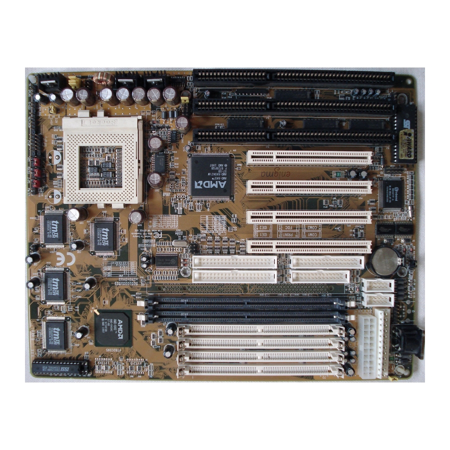
PREFACE HOT-603 mainboard is a highly integrated IBM PC/AT compatible system board. The design will accept AMD K5, K6, Intel Pentium P54C, Pentium MMX and Cyrix/IBM 6x86, 6x86L, 6x86MX processors and also features high-performance pipelined burst secondary cache memory support with size of 1024KB or 512KB. The memory sub- system is designed to support up to 512 MB of EDO RAM, Standard Fast Page DRAM and SDRAM in standard 72-pin SIMM socket and 168-pin 3.3 V DIMM socket. -
Page 4: Chapter 1 Features
FEATURES The HOT-603 Mainboard is carefully designed for the demanding PC user who wants high perfor- mance and many intelligent features in a compact package: AMD Chipset: Features AMD-640 Chipset with I/O subsystems. CPU Support: AMD K6 166~266 MHz, K5 PR75~PR166,... - Page 5 ACPI: Support ACPI (Advanced Configuration and Power Interface) function. ACPI provide more Energy Saving Features for the future operating system supporting OS Direct Power Management (OSPM) functionality. Board Size: 3/4 baby AT compact size 220mm x 280mm.
-
Page 6: Accessories Of Hot-603
ACCESSORIES OF HOT-603... -
Page 7: Chapter 2 Hardware Configuration
Hardware Configuration Jumper Setting Jumper pin headers show on right side are used to configure system clock, CPU multiplier and CPU voltages. System Clock - JC1 JC1 is a 6-pins header jumper which is used to adjust System Clock from 50MHz to 83 MHz. -
Page 8: Cpu Clock Configurations - Jc1, Jp3, Jp2 And Jp1
CPU Clock Configuration - JC1, JP3, JP2 and JP1 System Multiplier Processors Clock JP3 / JP2 / JP1 / Multiplier 66 MHz AMD-K6 266 MHz AMD K6 233 MHz, 66 MHz Pentium MMX 233 MHz. x 3.5 Cyrix/IBM 6x86MX PR266 AMD-K6 200 MHz, AMD-K5 PR200, 66 MHz... -
Page 9: System Clock And Cpu Multiplier On Hot-603
System Clock and CPU Multiplier on HOT-603 For whom like to set up system manually, listed tables show all the System Clock and CPU Multiplier that HOT-603 can offer. Table 2-2 shows the System Clock from 50 MHz to 83 MHz. -
Page 10: Cpu Voltage Configuration - Jpw!, Jv2, Jv3 And Jv4
CPU Voltage Configuration - JPW1, JV2, JV3 and JV4 Voltage Jumper-Setting CPU Type Type Vcore JPW1 3.52V AMD K5 ABx, 3.52V 3.52V Pentium P54C VRE, Cyrix/IBM 6x86 Single Pentium P54C STD, 3.3V 3.3V Cyrix/IBM 6x86 3.45V AMD-K6 3.2V 3.3V 233 / 266 MHz AMD-K6 2.9V 3.3V... -
Page 11: Flash Eeprom Vpp - Jvrom1
Flash EEPROM Vpp - JVROM1 HOT-603 mainboard supports two types of Flash EEPROM: 5 volt and 12 volt. By setting up jumper JVROM1, the main board can use both 5V or 12V flash EEPROM with new system BIOS files as they come available. -
Page 12: Power Supply Type Select
Power Supply Type Select HOT-603 provide both AT and ATX power connector on-board, AT and ATX power supply are available on HOT-603. Jumper AT-P is used to set what type of power supply is pluged to the main board. Power Supply Type... -
Page 13: Connectors & Sockets
6 pins PS/2 mouse header for optional PS/2 mouse cable. Diagram on the right side indicates the pinout of the 6-pin header. HOT-603 mainboard supplies two types of optional PS/2 mouse adapter cable, type 1 have 6-holes plug with hole 2 and hole 6 wireless;... - Page 14 The system power can be controlled by a momentary switch connector. Pushing the switch button will turn the system off . Note: When a AT Power Supply is used to HOT-603, please do not connect any momentary switch to PWRBTN1.
-
Page 15: Chapter 3 Memory Configuration
Memory Configuration The HOT-603 mainboard provides four 72-pin SIMM sockets and three 168-pin DIMM sockets that make it possible to install up to 512MB of RAM. The SIMM socket support 4MB, 8MB, 16MB, 32MB, 64MB and 128MB 5V single- or double-side fast page or EDO DRAM modules, and DIMM socket support 8MB, 16MB, 32MB, 64MB, and 128MB 3.3V single- or double-side SDRAM, fast page,... - Page 16 SIM 1 SIM 2 SIM 3 SIM 4 DIM 1 DIM 2 DIM 3 TOTAL 4 MB 4 MB —— —— —— —— —— 8 MB 4 MB 4 MB 4 MB 4 MB —— —— —— 16 MB 8 MB 8 MB ——...
-
Page 17: Chapter 4 Flash Utility
Flash Utility This chapter briefly discusses Award Flash utility provides instructions to guide you through updating your old BIOS. The file name we use to program here is test.bin, and the file name to save old BIOS is 603.OLD. Please note that those file names are not absolute. - Page 18 If “Yes” To save the old BIOS: 1. Please respond “Y”, and then press the ENTER key. 2. Move the cursor to “File Name to Save: “ 3. Type file name “603.OLD”, and then press the ENTER key. (Your old BIOS will be saved in the file name you create.
-
Page 19: Bios Setup
BIOS Setup HOT-603 BIOS ROM has a built-in Setup program that allows users to modify the basic system configuration. This type of information is stored in battery-backed RAM so that it retains the Setup information when the power is turned off. -
Page 20: Main Menu
Main Menu Standard CMOS setup This setup page includes all items in a standard compatible BIOS. BIOS features setup This setup page includes all items of Award special enhanced features. Chipset features setup This setup page includes all items of chipset features. Power Management Setup This setup page includes all items of Power Management features. - Page 21 Integrated Peripherals This setup page includes all items of peripheral features. IDE HDD auto detection Automatically configure IDE hard disk drive parameters. Supervisor Password Change, set, or disable supervisor password. It allows you to limit access to the system and Setup, or just to Setup. User Password Change, set, or disable user password.
-
Page 22: Standard Cmos Setup
Standard CMOS Setup Date The date format is <day>, <month> <date> <year>. Press <F3> to show the calendar. Time The time format is <hour> <minute> <second>. The time is calculated base on the 24-hour military-time clock. For example. 5 p.m. is 17:00:00. Hard Disks Type This item identify the types of hard disk drives that has been installed in the computer. - Page 23 Drive A type/Drive B type This item specifies the types of floppy disk drive A or drive B that has been installed in the system. Video This item selects the type of adapter used for the primary system monitor that must matches your video display card and monitor.
-
Page 24: Bios Features Setup
BIOS Features Setup Virus Warning When this item is enabled, the Award BIOS will monitor the boot sector and partition table of the hard disk drive for any attempt at modification. If an attempt it made, the BIOS will halt the system and the following error message will appear. Afterwards, if necessary, you will be able to run an anti-virus program to locate and remove the problem before any damage is done. - Page 25 Swap Floppy Drive When this item enables, the BIOS will swap floppy drive assignments so that Drive A: will function as Drive B: and Drive B: as Drive A:. Boot Up Floppy Seek During POST, BIOS will determine if the floppy disk drive installed is 40 or 80 tracks. Boot Up NumLock Status When this option enables, BIOS turns on Num Lock when system is powered on.
-
Page 26: Chipset Features Setup
Chipset Features Setup NOTE: Those item on this page are concering AMD-640 chipset timing, please do not try to adjust by yourself unless you are familiar with them. Auto Configuration This item auto configures the item of DRAM Timing Control. DRAM Timing Control will be set to "Auto"... - Page 27 OnChip USB This item is used to defined USB controller is "Enable" or "Disable". USB Keyboard Support This item is used to defined USB Keyboard is "Enable" or "Disable".
-
Page 28: Power Management Setup
Power Management Setup Power Management This item determines the options of the power management function. Max Saving puts the system into power saving mode after a brief period of system inactivity; Min Saving is the same as Max Saving except the time of the system inactivity period is longer;... - Page 29 HDD Power Down This item defines the continuous HDD idle time before the HDD enters power saving mode (motor off). The options are from 1 min to 15 min and Disabled. Doze Mode, Suspend Mode These items set the period of time after which each of these mode activate, the periods are from 1 min to 1 hour.
-
Page 30: Pci Configuration Setup
PCI Configuration Setup PNP OS Installed When this item is set to Yes, it will allow the PnP OS(Windows 95) control the system resources except PCI devices and PnP boot devices. Default setting is No. Resources Controlled By The Award Plug and Play BIOS has the capability to automatically configure all of the boot and Plug and Play compatible devices. - Page 31 PCI IRQ Activated by This item sets the method by which the PCI bus recognize that an IRQ service is being requested by a device. You should never change the default configuration unless advised otherwise by your System's manufacturer. Choices are Level(default) and Edge.
-
Page 32: Integrated Peripherals
Integrated Peripherals OnChip IDE First Channel This item is used to defined on chip Primary PCI IDE controller is Enable or Disable setting. OnChip IDE Second Channel This item is used to defined on chip secondary PCI IDE controller is Enable or Disable setting. - Page 33 KBC Input Clock This item specifies onboard keyboard controller clock input. default is 8 MHz. Onboard FDC Control This item specifies onboard floppy disk drive controller. This setting allows you to connect your floppy disk drives to the onboard floppy connector. Choose the "Disabled" settings if you have a separate control card.
- Page 34 RTC Power On (Date Ctrl) This item determine the date when system will resume from power-off. RTC Power On (Hour Ctrl) This item determine the hour when system will resume from power-off. RTC Power On (Minute Ctrl) This item determine the Minute when system will resume from power-off.
-
Page 35: Password Setting
Password Setting This section describes the two access modes that can be set using the options found on the Supervisor Password and User Password. Supervisor Password and User Password The options on the Password screen menu make it possible to restrict access to the Setup program by enabling you to set passwords for two different access modes: Supervisor mode and User mode. - Page 36 Password Disable If you select System at Security Option of BIOS Features Setup Menu, you will be prompted for the password every time the system is rebooted or any time you try to enter Setup. If you select Setup at Security Option of BIOS Features Setup Menu, you will be prompted only when you try to enter Setup.
- Page 37 HOT-603 AMD-K6 processor ™ Based PCI MAIN BOARD User's Manual...
Need help?
Do you have a question about the HOT-603 and is the answer not in the manual?
Questions and answers