Table of Contents
Advertisement
Quick Links
Advertisement
Table of Contents

Related Manuals for Shuttle HOT-661/P


Summary of Contents for Shuttle HOT-661/P
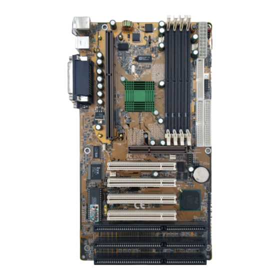
- Page 1 HOT-661/P Pentium II processor ™ Based AGP MAIN BOARD User's Manual - 46 -...
- Page 2 FCC Notice: This equipment has been tested and found to comply with the limits for a Class B digital device, pursuant to Part 15 of FCC Rules. These limits are designed to provide reasonable protection against harmful interference in a residential installation. This equipment generates, uses and can radiate radio frequency energy.
-
Page 3: Table Of Contents
TABLE OF CONTENTS ......................3 REFACE ..................4 HAPTER NTRODUCTION Specification..........................4 Accessories of HOT-661/P ......................6 ..............7 HAPTER ARDWARE ONFIGURATION The Pentium II Processor......................7 What does the URM (Universal Retention Mechanism) consist of..........8 Install the Universal Retention Mechanism and Heat Sink Support..........8 Install Pentium II Processor ......................10... -
Page 4: Preface
HOT-661/P provides a new level of I/O integration. Intel's 82440BX AGPset chipset provides increased integration and improved performance over other chipset designs. HOT-661/P main board provides an AGP slot to support a new generation of graphics cards with ultra-high memory bandwidth. -
Page 5: Chapter 1 Introduction
SPECIFICATION The HOT-661/P mainboard is carefully designed for the demanding PC user who wants high perfor- mance and many intelligent features in a compact package: Intel Chipset: Features Intel 440BX AGPset with I/O subsystems. CPU Support: Celeron processors 266/33 ~ 333/66 MHz... - Page 6 ACPI: Support ACPI (Advanced Configuration and Power Interface) function. ACPI provide more Energy Saving Features for the future operating system supporting OS Direct Power Management (OSPM) functionality. Board Size: ATX form factor, dimension 305mm x 170mm Advanced Features: Low EMI -- Spread Spectrum built in - ±1.5% modulation and automatic clock shut-off of unused PCI/SDRAMS slots to reduce the EMI.
-
Page 7: Accessories Of Hot-661/P
ACCESSORIES OF HOT-661/P - 6 -... -
Page 8: Chapter 2 Hardware Configuration
HARDWARE CONFIGURATION The Pentium™ II Processor The Pentium™ II and Celeron™ processor is the next member of the P6 processor family. It combines the architectural advances in the Pentium Pro processor with the instruction set extensions of MMX technology. It is fully compatible with the huge base of Intel architec- ture-based PC software. -
Page 9: What Does The Urm (Universal Retention Mechanism) Consist Of
(that is, no DIMMs, cables, or cards are installed). Install the Retention Mechanism : 1. Finds out the Universal Retention Mechanism (URM) Mounting Holes of Slot1 on HOT-661/P main board. (Refer to Figure 2-6) Figure 2-6 2. Install two Universal Retention... - Page 10 Install the Heat Sink Support: (optional) If your Heat Sink comes with the Heat Sink suport then install it according to the instruction comes with your Heat Sink. Figure 2-8 and Figure 2-9 shows some Heat Sink examples. Figure 2-8 Figure 2-9 - 9 -...
-
Page 11: Install Pentium Ii Processor
Mechanism. The latches must be secured for proper electrical connection of the proces- sor. Attach the end of the power cable to the three-pin connector on the mainboard or to the CPU fan connector on the HOT-661/P. Figure 2-10 Figure 2-11... -
Page 12: Celeron Processor S.e.p.p. Only Retention Mechanism Assembly Procedures
Celeron™ Processor S.E.P.P. Only Retention Mechanism Assembly Procedures These procedures have been included to help assemble the S.E.P.P. (Single Edge Processor Package) only Retention Mechanism. Please follow them exactly: Required Components Figure 2-13 SEPP (Figure 2-12) Primary Side Heatsink (Figure 2-13) Heatsink Retention Clip (Figure 2-14) Figure 2-12 Figure 2-14... -
Page 13: Install Celeron Processor
Install Celeron™ Processor Hold the processor unit so that the Heat sink faces toward the DIMM sockets on the mainboard. Insert the processor into the Universal Retention Mechanism. Press the processor down firmly with even pressure on both sides of the top until it is seated. (Refer to Figure 2-19 and Figure 2-20) Figure 2-19 Figure 2-20... -
Page 14: Install S.e.c.c.2 Processor
Install S.E.C.C.2™ Processor Hold the processor unit so that the Heat sink faces toward the DIMM sockets on the mainboard. Insert the processor into the Universal Retention Mechanism. Press the processor down firmly with even pressure on both sides of the top until it is seated. (Refer to Figure 2-21 and Figure 2-22) Figure 2-21 Figure 2-22... -
Page 15: Jumpers
CPU speed higher than 233 MHz or 350 MHz., you only have to entry BIOS to set CPU speed to the higher one. For the practiced user, HOT-661/P also provides Hard-Configure function to adjust your CPU Speed. You can adjust your CPU Host Clock on JP39 and adjust your CPU Clock Ratio on JP37 manually. - Page 16 CPU Clock Configuration Table (Table 2-1) shows the Pentium II/Celeron 233 MHz ~333 MHz and Pentium II 350 MHz ~ 450 MHz quick setting on the mainboard. Table 2-2 shows adjustable System clock on jumper JP39. Note: JP39 will be not available when jumper group JP37 is set to AUTO. Table 2-3 shows adjustable CPU Clock Ratios on jumper group JP37.
- Page 17 CPU Clock Ratio HOT-661/P mainboard provides a Jumper group JP37 to set CPU Speed configure by BIOS or by hardware jumper. By inserting jumper pack on AUTO group, the user can Soft-Configure the CPU Host Clock and CPU Clock Ratio from BIOS.
-
Page 18: Clear Cmos - Jp19
6) Turn on the PC. Flash EEPROM Vpp - J17 HOT-661/P mainboard supports two types of Flash EEPROM: 5 volt and 12 volt. By setting up jumper J17, the main board can use both 5V or 12V flash EEPROM with new system BIOS files as they come available. -
Page 19: Connectors
Connectors Front Panel Connectors Hardware Reset Connector - J32 Attach 2-pin hardware reset switch to it. Closing the reset switch restarts the system. PWR LED Connector - J27 Power LED connector is a 3-pin connector for attached to the case's Power LED. KeyLock Connector - J27 KeyLock connector is a 2-pin connector for a lock that may be installed on the system case for enabling... - Page 20 Back Panel Connectors Figure 2-27 COM1/COM2 Connectors Attach COM1/COM2 device cables to these connectors. PS/2 Keyboard & PS/2 Mouse Connector Two 6-pin female PS/2 keyboard & Mouse Connectors is located at the rear of the main board. PS/2 Mouse on top of connector and PS/2 Keyboard on the bottom of connector. Plug the PS/2 keyboard and mouse jack into this connector.
- Page 21 CPU, Chassis & AGP cooling Fan connectors - JP29, JP28, J43 & The main board provides three onboard 12V cooling fan power connectors for CPU (JP28 & JP29), Chassis (J43) and AGP device (J47) cooling fan. Depending on the fan maker, the wiring and plug may be different.
-
Page 22: Chapter 3 Memory Configuration
MEMORY CONFIGURATION The HOT-661/P mainboard provides four 168-pin DIMM sockets that make it possible to install from 8MB up to 1024MB of SDRAM. The DIMM socket support 8MB, 16MB, 32MB, 64MB, 128MB and 256MB3.3V single- or double-side SDRAM DIMM. The four DIMM sockets are arranged in four banks of one socket each, Each bank provides a 64/72-bit wide data path. -
Page 23: Chapter 4 Flash Utility
FLASH UTILITY This chapter briefly discusses Award Flash utility in order to guide you through updating your old BIOS. The file name we use to program here is test.bin, and the file name to save old BIOS is 661.OLD. Please note that those file names are not absolute. They are only examples to let you have a more clear understanding of the updating process. - Page 24 If “No” If you do not wish to save the old BIOS: 1. Please type “N”, and then press the ENTER key. 2. Then you will be requested to answer: “Are You Sure to Program? “ 3. Answer “N” if you do not want to program, and then it will exit. If “Yes”...
- Page 25 Notes About Award Flash Utility Please note that Award Flash Utility cannot run under EMM386 or QEMM. Thus, when executing the command “awdflash”, an error message will appear: “Error Message: Fail — Due to EMM386 or QEMM !” - 24 -...
-
Page 26: Chapter 5 Award Bios Setup
BIOS SETUP HOT-661/P BIOS ROM has a built-in Setup program that allows users to modify the basic system configuration. This information is stored in battery-backed RAM so that it retains the Setup information when ever the power is turned off. -
Page 27: The Main Menu
The Main Menu Standard CMOS setup This setup page includes all items in a standard compatible BIOS. BIOS features setup This setup page includes all items of Award special enhanced features. Chipset features setup This setup page includes all items of chipset features. Power Management Setup This setup page includes all items of Power Management features. - Page 28 IDE HDD auto detection Automatically configure IDE hard disk drive parameters. Supervisor Password Change, set, or disable supervisor password. It allows you to limit access to the system and Setup, or just to Setup. User Password Change, set, or disable user password. It allows you to limit access to the system and Setup, or just to Setup.
-
Page 29: Standard Cmos Setup
Standard CMOS Setup Date The date format is <day>, <month> <date> <year>. Press <F3> to show the calendar. Time The time format is <hour> <minute> <second>. The time is calculated base on the 24-hour military-time clock. For example. 5 p.m. is 17:00:00. Hard Disks Type This item identify the types of hard disk drives that has been installed in the computer. - Page 30 Video This item selects the type of adapter used for the primary system monitor that must matches your video display card and monitor. Although secondary monitors are sup- ported, you do not have to select the type in Setup. Error halt This item determines if the system will stop, when an error is detected during power up.
-
Page 31: Bios Features Setup
BIOS Features Setup Virus Warning When this item is enabled, the Award BIOS will monitor the boot sector and partition table of the hard disk drive for any attempt at modification. If an attempt it made, the BIOS will halt the system and the following error message will appear. Afterwards, if necessary, you will be able to run an anti-virus program to locate and remove the problem before any damage is done. - Page 32 Swap Floppy Drive When this item enables, the BIOS will swap floppy drive assignments so that Drive A: will function as Drive B: and Drive B: as Drive A:. Boot Up Floppy Seek During POST, BIOS will determine if the floppy disk drive installed is 40 or 80 tracks. Boot Up NumLock Status When this option enables, BIOS turns on Num Lock when system is powered on.
- Page 33 Video BIOS Shadow Determines whether video BIOS will be copied to RAM. However, it is optional depending on chipset design. Video Shadow will increase the video speed. C8000-CBFFF Shadow/DC000-DFFFF Shadow These categories determine whether option ROMs will be copied to RAM. An example of such option ROM would be support of on-board SCSI.
-
Page 34: Chipset Features Setup
Chipset Features Setup Auto Configuration The default setting of the optimal timings for items 3 through 7 for 60ns EDO DRAM modules. DRAM Speed Selection This item set the EDO DRAM Read/Write timings that the system uses. When item of "Auto Configuration"... - Page 35 EDO DRAM Read Burst ) This item set the EDO DRAM Read Burst Timing. The timing used depends on the type of DRAM (EDO burst mode or standard fast page mode) on a per-bank basis. The options are 222 and 333. EDO DRAM Write Burst This item set the EDO DRAM Write Burst timing for accessing DRAM.
- Page 36 Passive Release When enabled, the chipset provides a programmable passive release mechanism to meet the required ISA master latencies. Delayed Transaction Since the 2.1 revision of the PCI specification requires much tighter controls on target and master latency. PCI cycles to or from ISA typically take longer. When enabled, the chipset provides a programmable delayed completion mechanism to meet the required target latencies.
- Page 37 CPU Clock Ratio This item allows the user to adjust CPU Host Clock/Internal Clock ration when JP37 is set to Auto. The user may adjust CPU Clock Ratio from x2 to x5. This item will not show up when JP37 is set to Manual. CPU Speed This item is show only.
-
Page 38: Power Management Setup
Power Management Setup ACPI Function This item determine to support ACPI function or not. Power Management This item determines the options of the power management function. Max Saving puts the system into power saving mode after a brief period of system inactivity; Min Saving is the same as Max Saving except the time of the system inactivity period is longer;... - Page 39 MODEM Use IRQ This item determines the IRQ in which the MODEM can use. The choice: 1, 3, 4, 5, 7, 9, 10, 11, N/A. Doze Mode When enabled and after the set time of system inactivity, the CPU clock will run at slower speed while all other devices still operate at full speed.
- Page 40 ** Reload Global Timer Events ** If any of these items is set to Disabled, that system activity event will not be monitored to reload global timer. If these items is set to Enabled, that system activity event will be monitored to reload global timer. These items include IRQ[3-7, 9-15], NMI, Primary IDE0/1, Secondary IDE 0/1, Floppy Disk, Serial Port and Parallel Port.
-
Page 41: Pci Configuration Setup
PCI Configuration Setup PNP OS Installed When this item is set to Yes, it will allow the PnP OS(Windows 95) control the system resources except PCI devices and PnP boot devices. Default setting is No. Resources Controlled By The Award Plug and Play BIOS has the capability to automatically configure all of the boot and Plug and Play compatible devices. - Page 42 PCI IDE IRQ Map to This items allows you to configure your system to the type of IDE disk controller in use. By default, Setup assumes that your controller is an ISA device rather than a PCI control- ler. If you have equipped your system with a PCI controller, changing this allows you to specify which slot has the controller and which PCI interrupt (A, B, C or D) is associated with the connected hard drives.
-
Page 43: Integrated Peripherals
Integrated Peripherals IDE HDD Block Mode This item is used to set IDE HDD Block Mode. If your IDE Hard Disk supports block mode, then you can enable this function to speed up the HDD access time. If not, please disable this function to avoid HDD access error. - Page 44 IDE Primary Master UDMA On this mainboard, Intel 440BX PCIset improves IDE transfer rate using Bus Master UltraDMA/33 IDE which can handle data transfer up to 33MB/sec. The options are Disabled, Enabled and Auto, Auto is the default settings for on board Primary Master UltraDMA33.
- Page 45 Hot-Key - Power-on by soft-on/off button and keyboard are available. The user may set power-on hot-key from <Ctrl><F1> to <Ctrl><F12>. PS/2 Mouse - Powre-on by soft-on/off button and PS/2 Mouse are available. Note:1. When item of PS/2 Mouse or HOT-Key is selected, please also adjust jumper JP38 and J44 to the proper position.
-
Page 46: Password Setting
Password Setting This section describes the two access modes that can be set using the options found on the Supervisor Password and User Password. Supervisor Password and User Password The options on the Password screen menu make it possible to restrict access to the Setup program by enabling you to set passwords for two different access modes: Supervisor mode and User mode.
Need help?
Do you have a question about the HOT-661/P and is the answer not in the manual?
Questions and answers