
Related Manuals for Cambo RPS-SYSTEM


Summary of Contents for Cambo RPS-SYSTEM
- Page 1 RPS-SYSTEM Motorized reproduction column INSTRUCTION MANUAL Please read this manual carefully before using the RPS-SYSTEM...
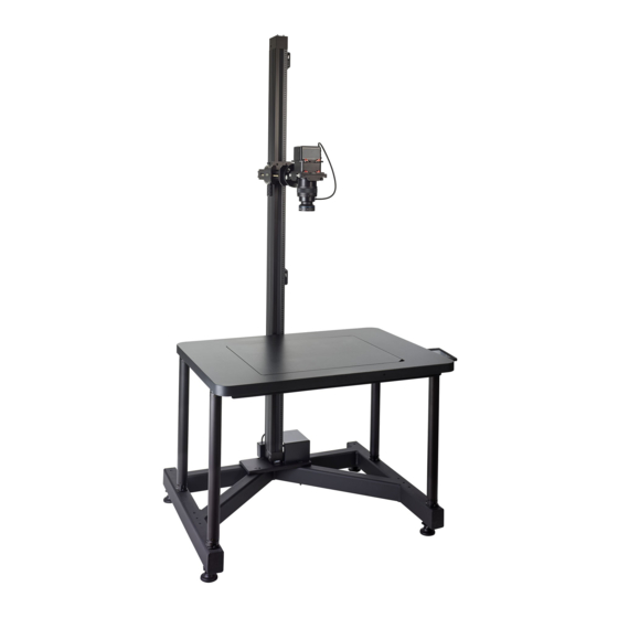
- Page 3 Thank you for purchasing a Cambo product. Cambo's motorized Column for Reproduction Photography, RPS-System, is a user friendly system that can be configured from different elements to ensure the best possible solution for any reproduction photography situation. The vertical movement is self-locking, motorized and remote controlled by a control unit which also controls the speed an direction of the column.
-
Page 4: Table Of Contents
Index Warnings ..................3 Key features ................4 RPS-System overview ..............5 Setting up the RPS-System ............6 4.1 Unpacking the base ..............6 4.2 Levelling the base ............... 7 4.3 Applying the column to the base ..........7 4.4 Levelling the column ..............8 4.5 Applying the board to the base ........... -
Page 5: Warnings
Warnings The motorized column features two height adjustable end-stops. When the cross-arm passes one of these end-stops the drive immediately stops. When positioned correctly these end-stops prevent collisions between the cross-arm or camera and the baseboard, floor, ceiling or object on the baseboard. -
Page 6: Key Features
Key features • Motorized vertical adjustment • Fine geared horizontal adjustable camera arm • Adjustable motor speed • Automatic end stops • Self-locking vertical position • Reinforced aluminium column • Wall mounting options • Optional base... -
Page 7: Rps-System Overview
B. RPS-175 Cross arm extension C. RPS-180 Levelling unit pro D. RPS-160 Board Basic RPS E. RPS-222 Kit Height adjusters F. RPS-Base G. RPS-170 Wall mount Kit H. RPS-201 Smart controller RPS-Remote controller J. RPS-Control box Figure 1 RPS-System overview... -
Page 8: Setting Up The Rps-System
Setting up the RPS-System Unpacking the base CAUTION, when removing or placing the baseboard from or to the base It’s advised to perform the following instructions with two persons. Please remove or insert the baseboard uniformly distributed and parallel to the base to prevent jamming. -
Page 9: Levelling The Base
Levelling the base Figure 3 Leveling the Base To correctly level the RP1-Base you will have to use a spirit level [A]. The base features four adjustable feet [B]. To level the base, loosen locking ring [D] then use a spanner (metric 14mm) to adjust the height of the feet by turning nut [C]. -
Page 10: Levelling The Column
Figure 4 Mounting the column to the base Levelling the column Use a spirit level [detail D]l to check if the column is leveled. Make sure the base is correctly leveled first. Please only perform this operation when necessary. If the column is slightly off, the four set screws [D] near the bolts [A] can be used to fine adjust the level of the column. -
Page 11: Applying The Board To The Base
Applying the board to the base It is advised to perform the baseboard placement with two persons. 4.5.1 Applying the baseboard with extenders Before applying the extenders to the base, make sure all the setscrews [D] and [E] are fully loosened. Place the four extenders [C] in the base couplers [B]. -
Page 12: Wall Mount Installation
For fine tuning the position of the column both the top and bottom bracket contain a set screw [E]. Before using the set screws, slightly loosen bolts [D] then tighten or loosen set screws [E]. when the column is leveled, retighten bolts [D]. Figure 7 RPS-System wall mount... -
Page 13: Connecting The Rps-System
Connecting the RPS-System Please ensure to read the safety warnings [Chapter 1] carefully before connecting and operating the RPS- system. Interface and connections 5.1.1 Column interface a. Cross-arm b. Cross-arm drive knob c. Cross-arm locking knob d. Arca compatible Quick release e. -
Page 14: Remote Control Interface
5.1.2 Remote control interface a. Pushbutton UP b. Pushbutton DOWN c. Low/High mode indication light d. Low/High mode pushbutton switch e. Speed control potentiometer f. Remote control cable socket g. Magnetic back h. Weight compensation potentiometer* Figure 9 Remote control Because of the weight of the camera, the downward speed will be higher than the upward speed. -
Page 15: Rps-Connection Scheme
RPS-connection scheme Figure 11 RPS-Connection scheme WARNING!: Before connecting the AC cable, please determine if the input power specified on the power supply corresponds with the AC power used in your area WARNING!: Never unplug any of the connectors when the unit is in use, this may damage the electronics. - Page 16 This instruction manual is prepared with care, although no responsibility, financial or otherwise, is accepted for any consequences related the information stated in this instruction manual. All specifications in this instruction manual are subject to change without notice. For more information please visit the Cambo web site: www.cambo.com...
Need help?
Do you have a question about the RPS-SYSTEM and is the answer not in the manual?
Questions and answers