Table of Contents
Advertisement
Advertisement
Table of Contents

Related Manuals for WEISS WBL290F


Summary of Contents for WEISS WBL290F
-
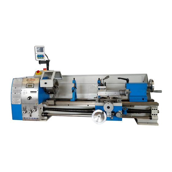
Page 1: Headstock & Taiistock Aiignment
WBL290F 11-1/2" x 29" METAL LATHE with DRO User Manual... -
Page 2: Table Of Contents
TABLE OF CONTENTS GeneraI Safety Instructions ....................3 Specific Safety Instructions ....................4 Features ............................ 5 PhysicaI Features........................6 Set-Up ............................7 Un-Packing & Inventory ......................7 Proper Grounding........................8 Chuck ............................9 Steady Rest ..........................9 FoIIow Rest ..........................10 Lathe Bed .......................... -
Page 3: Generai Safety Instructions
General Safety Instructions For Machines E xtrem e cau tion should be used w he n ope rating all po w er tools. K no w you r po w er tool, be familiar w ith its ope ra tion , read throug h the user m a n u a l and p ra ctice sa fe usage procedures at all times. -
Page 4: Specific Safety Instructions
W BL290F - M ETAL LATHE SP EC IFIC SA FETY IN STRU C TIO N S broken parts, and any other conditions This machine is designed and that may effect the tooIs operation. intended for use by properly trained and experienced personnel Remove adjusting keys... -
Page 5: Features
"MODEL WBL290F - 11-1/2" x 29" METAL LATHE WITH VARIABLE SPEED. As part of the growing Line of WEISS metalworking equipment, we are proud to offer the WBL290F a 11-1/2" x 29" MetaI Lathe with Digital Readout. By following the instructions and procedures Laid out in this user manual, you wiII receive years of excellent service and satisfaction. -
Page 6: Physicai Features
WBL290F -METAL LATHE PHYSICAL FEATURES A. Variable Speed Switch N. Half Nut Lever B. ON/OFF Switch O. Auto Feed Lever C. Forward/Reverse Switch P. Cross Slide Hand Wheel D. Emergency Stop Switch Q. Carriage Hand Wheel E. 3-Jaw Chuck R. Lead Screw S. -
Page 7: Setup
I. Reduce Sleeve (No. 5/3). J. Oil Gun WARNING K. Toolbox WBL290F is a very heavy L. Wedge Type Quich Change Tool Post 1 machine, do not over-exert M . W renches (8-10, 12-14, 17-19). N. Hex Wrenches (3,4,5,6,8) yourself. -
Page 8: Proper Grounding
Improper connection of the equipment- the risk of electric shock. grounding conductor can result in a risk WBL290F is equipped with a 110-V single of electric shock. Check with a qualified phase motor. electrician if you are in doubt as to To prevent electrical hazards, have a whether the outlet is properly grounded. -
Page 9: Chuck
CHUCK WBL290F comes equipped with a 160mm, 3-jaw chuck, and a 270mm face plate. Secure the steady rest to the lathe bed from below with a locking plate. The 3-jaw chuck is a scroll type chuck, meaning that all three jaws move in... -
Page 10: Foiiow Rest
The sliding fingers of the steady rest shown two precision ground V-side ways in figure-5 should receive periodic lubrication are re- enforced by heat hardening when used, to prevent premature wear. and grinding to guide the carriage and the tailstock accurately. The main FOLLOW REST motor is mounted to the rear of the left side of the bed. -
Page 11: Gearbox
GEARBOX FORWARD / REVERSE SWITCH: The gearbox is located on the left side of After the machine is switched ON, the lathe and is mounted on the bed. It is turn the switch to "F" position for used to select the feeds for straight counter-clockwise spindle turning rotation (forward). -
Page 12: Apron
SADDLE The saddle is made from high quality cast iron and all sliding parts are smoothly ground to fit the V on the bed without play. Figure-12 Gearbox controls V AR IAB LE SP E E D C O N T R O L KN O B : Tum the knob clockwise to increase the spindle speed and counter-clockwise to decrease the spindle speed. -
Page 13: Carriage Controis
360。 if needed. See figure- 15. threading process. See figure-16. Tool post: A wedge type quick change post is supplied with WBL290F. Cutting tooIs can be attached and removed by tightening or Ioosening the cIamping boIt. See figure- 15. -
Page 14: Taiistock
Tailstock Controls Tailstock The taiIstock slides on a V-way and can be Tailstock Hand Wheel: Turning the champed at any location. The tailstock has hand wheeI advance or retracts the quill in a heavy duty spindle and the spindle can the taiIstock. -
Page 15: Test Run
Test Run Once you have assembled your lathe while test running the machine, check the completely, it is then time for a test run to following: make sure that the lathe works properly and is ready for operation. The Emergency Stop & ON/OFF buttons are working properly. -
Page 16: Speed Change
The speed settings available on the WBL290F are 50 - 850 RPM and 110 - 1800 RPM. Figure-23 Screws and nuts securing the motor mounting plate To Change The Spindle Speed Unscrew the two fastening knobs shown in Position the belt on the pulleys for high and figure-22 and remove the protective cover. -
Page 17: Longitudinai Turning With Auto-Feed
Longitudinal Truing With Manual Longitudinal Auto.Feed Turning Set the feed direction selector knob and In this turning operation, the tooI feeds feed rate selector knob shown in figure-25 paraIIeI to the axis of rotation (IongitudinaI) to select the feed direction and feed speed. work-piece. -
Page 18: Turning Between Centers
Turning Between Centers Imperial Thread: when cutting inch threads, the half nut and threading dial are For turning between centers, it is necessary used to thread in a conventional manner. to remove the chuck from the spindle. Fit The threading and feeding table on page-27 the MT3 center into the 5/3 reducing sleeve or on the headstock, specifies at which (provided) and fit the reducing sleeve into... -
Page 19: Change Gears Repiacement
Left And Right Thread Cutting: The left Select the proper gear set according to your and right thread cutting is done using requirements from the feed table given on the feed direction selector knob. lathe (See page-27 Threading & Feeding Table for details) and install it onto Turning the feed direction selector knob the quadrant using nuts removed. -
Page 20: Top Siide Gib Screws Adjustment
Remove the bolts, securing the back plate Top Slide Gibs Adjustment to the chuck. Tap along the edge of the Locate the adjustment gibs on the side of mounting shoulder until the chuck and back the top slide as shown in figure-36. Loosen plate are free of each other and thread back the nuts holding the gibs and then tighten plate onto the spindle. - Page 21 The finished diameter of the shoulder should 0.025mm larger than diameter of the recess in the chuck. This is a critical step in minimizing chuck run-out. Re-install the chuck and check for run-out. Headstock & Tailstock Alignment The headstock and taiIstock alignment has been adjusted properly in the factory before Figure-37 Stock thicker at the taiIstock end the machine is shipped to you.
-
Page 22: Main Spindie Bearings
Re-tighten the two hex socket cap screws. CAUTION Make sure not to tighten the hex socket cap screws excessively or it will damage the bearing. Lubrication Figure-39 TaiIstock offset adjustment screw Lubricate all slide-ways lightly before every use with 20w oil. Turn another 0.5mm off the stock and check for taper. -
Page 23: Change Gears
Saddle To drain the oil, remove the drain plug on the left side of headstock. See figure-45. Lubricate the four oil ports (A) shown in Drain completely and refill after first three figure-47 with 20w machine oi once daily. months of operation. Then, change oil in the headstock annually. -
Page 24: Lead Screw
Maintenance Lead screw Lubricate the oil ports (D & E) shown in During the life of your machine, you will figure-46 with 20w machine oil once daily. need to practice some regular maintenance to keep your lathe in peak performance condition. -
Page 25: Optionai Chip Tray & Stand
Optional Stand The WBL290F features an optional stand Model WBL290FST which can be bought separately. Figure-49 Mounting the Iathe on the stand Once both the brackets are properly secured to the cabinets, position the chip Figure-48 WBL290F Stand inventory tray on the cabinets aligning the holes on the chip tray with the holes on the cabinet. -
Page 26: Eiectricai Connections & Wiring Diagram
Electrical Connections Warning Connection of the lathe and all other The WBL290F Variable speed lathe is rated at 2- electrical work may only be carrier out by Horse power, Single phase, 110V-Volt. Use the authorized electrician.Failure wring diagram for connecting the lathe to the comply may cause serious injury and main supply. -
Page 27: Threading & Feed Tabie
Threading & Feed TabIe... -
Page 28: Troubieshooting
WBL290F Troubleshooting Problem Problem reason Elimination Surface of workpiece too Tool blond Resharpen tool rough Tool Springs Clamp tool with less overhang Feed too high Reduce feed Radius all the tool lip too small Increase radius Workpiece becomes coned Centers are not aligned(Tailstock... - Page 29 PARTS LISTS...
- Page 31 Headstock and Driving Assembly...
- Page 32 Headstock and Driving Assembly(I) Parts No. Description Specification Headstock Headstock panel Screw M4x8 Fixed block Screw M6x16 Screw M6x20 Spindle Thin flat key 8x45 Gasket Bearing 32011/P5 Gasket Gasket Bearing 32010/P5 Gasket Bead sleeve Bead Gear Spindle pulley Gasket Spindle lock nut Screw M5x10 Belt...
- Page 33 Headstock and Driving Assembly (II) Parts No. Description Specification Screw M6x16 Chuck cover bearing M5x25 Screw Screw M6x5 Shaft Chuck cover Lock cam Spring Screw M8x16 Speed display Governor potentiometer Velocity probe Probe holder Screw M4x16...
- Page 34 Gearbox Assembly Gearbox Assembly...
- Page 35 Gearbox Assembly (I) Parts No. Description Specification Output shaft 4x12 Bearing sheath Bearing 51103 Bearing SF-1-1615 O-Ring 16x2.4 Bearing SF-1F16170 Gear Collar Gear Shaft 5x12 Bearing 6202 Left Plug Hex Socket Cap Screw M5x12 Snap Ring Φ14 Collar O-Ring 18x2.4 Snap Ring Φ18 Bearing...
- Page 36 Parts No. Description Specification Bearing SF-1-1615 Gear Snap Ring Φ16 Bearing 1610 Left Plug Fork Bracket Φ3X20 Shaft O-Ring 6.7x1.8 Fork Gear T16 / T32 / T24 Collar Bearing SF-1-1210 Gear Right Plug Dials Block Gearbox Cover Φ5x40 Knob Base Knob Label Ball...
- Page 37 Top slide Cross slide , Carriage Assembly...
- Page 38 Top slide Cross slide , Carriage Assembly ( I ) Parts No. Description Specification Screw M8x30 Handle base CQ6230-07-20 Handle lever CQ6230-07-21 washer CQ6132GV-07-19 Tool slide CQ6132GV-07-23 Stop CQ6230-07-16 Spring CQ6230-07-48.1 Top slide CQ6230-07-24 (b) CQ6230-07-38 Beadring 51101 Bracket CQ6230-07-28c Graduated dial CQ6230C-07-29E Handwheel...
- Page 39 Top slide Cross slide , Carriage Assembly ( Ⅱ ) Parts No. Description Specification Back clamp plate CQ290V-07-22 Hex Socket Cap Screw M8x30 Front right clamp plate CQ290V-07-23 Front left clamp plate CQ290V-07-24 Bracket CQ6132V-07-26 Hex Socket Cap Screw M8x20 Washer Collar CQ290V-07-25...
- Page 40 Apron Assembly...
- Page 41 Apron Assembly ( I ) Parts No. Description Specification Gear Φ5x24 Gear Washer Set Screw M4x8 Gear Shaft Shaft Snap Ring Φ8 Gear Shaft Gear Gear Φ4x16 Gear Washer Gear Gear Snap Ring Φ15 Shaft Worm 5x14 Gear Washer Worm Bearing 2501 Worm Base...
- Page 42 Apron Assembly (II) Parts No. Description Specification Hex Socket Cap Screw M6x8 Ball Φ5 Spring 0.7x4x10 Set Screw M6x6 Knob Handle Handle Base Φ5x45 Shaft Base Hex Socket Cap Screw M5x10 Shaft Handle Shaft Forx Φ5x20 Base Set Screw Knob Hex Socket Cap Screw M5x35 Shaft Handle...
- Page 44 Tailstock Assembly Parts No. Description Specification Tailstock quill Hex Socket Cap Screw M4x10 Lead Screw 3x10 Pivot Block Washer Φ10 Lever M10-95x50 Oil Ball Φ6 Tailstock body Collar Set Screw M6x10 Limit Screw M6x10 Flange Cover Hex Socket Cap Screw M5x12 Graduated Dial Spring...
- Page 45 Bed Assembly...
- Page 46 Parts No. Description Specification Rack Hex Socket Cap Screw M6x16 Φ5x20 Feed Shaft Shaft Bracket Bearing 51102 Washer Φ12 M12x1.25 Hex Socket Cap Screw M6x45 Oil Ball Φ6 Φ3x20 Hex Socket Cap Screw M8x40 Chip Pan Chip Shield Washer Φ6 Hex Socket Cap Screw M6x16...
- Page 47 ELECTRICAL BOX ASSEMBLY...
- Page 48 ELECTRICAL BOX ASSEMBLY Parts No. Description Specification Timing Knob Screw Lable R/F Swich ZH-A EN61058 Speed Display Optional Screw Magnetic Swich Screw Electrical Plate Potentiometer WX 14-12 Electrical Box Emergency Stop XB2-BS542 Limited Switch LXW5-11Q1 Speed Control Board Cover Screw Fuse Holder Fuse (10A) Strand Relief...
Need help?
Do you have a question about the WBL290F and is the answer not in the manual?
Questions and answers