
Related Manuals for WEISS Pick-O-Mat PM1100


Summary of Contents for WEISS Pick-O-Mat PM1100
- Page 1 PICK-O-MAT ASSEMBLY AND INSTRUCTIONS MANUAL Mechanical system documentation Pick-O-Mat PM1100 / PM1500 TD0044A-EN00-0000-00 ENE 02-2014...
- Page 2 All rights in this document are the copyright of WEISS GmbH. This document may not be copied or reproduced, in whole or in part, without the written permission of WEISS GmbH. This document is only intended for the user of...
-
Page 3: Table Of Contents
Table of contents Introduction ......................5 1.1. Definition ..................... 5 1.2. Intended use ....................5 1.3. Non-intended use ..................5 1.4. Laws / EC Directives / Standards .............. 5 1.5. Further applicable documents ..............6 1.6. Assembly and instructions manual ............6 1.6.1. - Page 4 5.3. Assemble machine ................... 22 5.3.1. Assembly with base body ................22 5.3.2. Assembly without base body ..............22 5.3.3. Mounting the adapter plate ................. 23 5.3.4. Electrical installation ................... 24 5.3.5. Installing the safety equipment ..............24 5.4. Instructions on disposal of packaging material ........24 Commissioning ....................
-
Page 5: Introduction
Introduction 1.1 Definition Introduction Definition The Pick-O-Mat is an automatic assembly machine. The axes carry out cycled move- ments. Devices for handling loads are mounted to the axes by the customer. In the following text of the document, the assembly machine will be referred to as "module". -
Page 6: Further Applicable Documents
The specifications stated in these documents must to be observed. • TC0320T rotary indexing table, operating instructions • TR1100A rotary indexing table, operating instructions For control system by WEISS-GmbH: • Operating manual of the employed controller Assembly and instructions manual 1.6.1... -
Page 7: Explanation Of Safety Instructions In This Manual
Introduction 1.7 Warranty and liability 1.6.2 Explanation of safety instructions in this manual This manual contains instructions that you should observe for your personal safety and to avoid material damage. Safety instructions for your personal safety are highlighted by a sign containing a warning triangle and signal word. -
Page 8: Safety
Safety 2.1 Fundamental safety instructions Safety Fundamental safety instructions 2.1.1 Operator‘s obligation to exercise diligence This machine conforms to state-of-the-art technological standards and ensures a maxi- mum level of safety. However, this level of safety can only be attained under operating conditions if all measu- res necessary for this have been taken. -
Page 9: Requirements To Be Met By Personnel
Safety 2.2 Safety equipment for the machine 2.1.2 Requirements to be met by personnel It is imperative that the following safety instructions be observed during all operations involving the machine. This ensures avoidance of life-threatening injuries, machine damage, other material damage and environmental damage. The personnel must ensure that •... -
Page 10: Residual Hazards
Safety 2.3 Residual hazards Residual hazards WARNING Employing of technicians is required Tasks such as assembly, commissioning, troubleshooting, maintenance and disas- sembly require special qualifications of the personnel. Such work may be carried out only by technicians that have been authorised by the operator to do so. Injuries can be caused due to mistakes by unauthorised personnel being employed. -
Page 11: Product Description
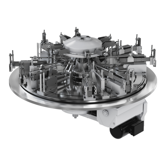
Product description 3.1 Structure Product description Structure The module is a combination of various mechanical and electromechanical components. The assembly consists of: Kinematics Handling modules Central drive for the kinematics Lift modules (not shown) Press modules (not shown) Rotating device On PM1100: Rotary indexing table TC0320T with rotary disc On PM1500: Ring rotary indexing table TR1100A with rotation swivel For construction and function of the rotating device, refer to the supplied documentation... -
Page 12: Function
Product description 3.2 Function Function 3.2.1 Complete module The kinematics converts the rotation of a double curve driven by the central drive and creates the horizontal and vertical movements of the handling modules. A three-phase motor with attached closed-circuit brake (braked without voltage) drives the double curve via a toothed belt segment and reduction gear. -
Page 13: Movement Sequence
Product description 3.3 Movement sequence Movement sequence To control the Pick-o-Mat, all other switch and query points such as "start rotary indexing table", "gripper open", "gripper closed", "query round table in pos." need to be controlled in coordination with the insertion movements. The position of the handling modules is signalled by a position encoder on the control cam. -
Page 14: Crash Safety
Additional barcode serial number Type type PMXXXX Serial Number serial PMXXXXXX year XXXX Year of construction XX kg weight www.weiss-gmbh.de Weight Fig. 5: Example of a type plate 14/44 Pick-O-Mat • PM1100 / PM1500 • R02-2014... -
Page 15: Scope Of Delivery
Product description 3.5 Technical data 3.5.3 Scope of delivery The scope of delivery of the machine depends on the order involved. Please refer to the order information or order specifications for individual components. 3.5.4 Weight Weight of the Pick-o-Mat assembly machine: < 1000 kg 3.5.5 Sound level The A-weighted emission sound pressure level does not exeed the allowable peak. -
Page 16: Installation Positions
Product description 3.5 Technical data 3.5.8 Installation positions Approved installation position: • horizontal Fig. 6: Installation positionPM1100 / PM1500 16/44 Pick-O-Mat • PM1100 / PM1500 • R02-2014... -
Page 17: Dimensions
Product description 3.5 Technical data 3.5.9 Dimensions 1050 1050 0 * Standard dimension (other values aviable according to order) +0,02 +0,02 +0,03 +0,03 Fig. 7: Dimensions PM1100 1210 1210 1500 * Standard dimension (other values aviable according to order) 1174 1174 1140 1140... -
Page 18: Transport
Transport 4.1 Appliances and auxiliary equipment approved for transportation Transport WARNING Falling or sagging loads can lead to grievous injuries. Inadequately dimensioned load bearing equipment can break. Transport vehicles not designed to support the weight of the machine may fail or topple over. Lifting devices, conveyor vehicles (pallet trucks) and load carrying equipment should conform to regulations and be designed to support the weight of the machine including packaging. -
Page 19: Transporting Of The Unpacked Machine
Transport 4.2 Transport damage 4.1.2 Transporting of the unpacked machine Risk of injury emanating from falling machine. Shackles need to be used for transporting the unpacked machine. The shackles are screwed onto the standing middle part. The hoisting cables can be fastened to the eyes of the shackles. -
Page 20: Intermediate Storage
Transport 4.3 Intermediate storage Intermediate storage Observe the storage conditions listed in the following table, if intermediate storage is planned for a longer period of time. Climatic Packaging Storage location Storage duration zone Packed in contai- ners With moisture absorbers and Roofed over Max. -
Page 21: Installation
Installation 5.1 Safety during installation Installation Safety during installation WARNING Injuries caused by incorrect installation. The dimensions of the supporting ground and fastening equipment must sufficient, so that they can withstand the stresses produced during operation. Auxiliary personnel may only perform work which is assigned to them by plant techni- cians. -
Page 22: Installation Preparation
Installation 5.3 Assemble machine 5.2.1 Installation preparation • Open the packaging unit prior to the assembly and remove the machine from the packaging unit. • The attachment screws must be at hand. 5.2.2 Operating media / Auxiliary media / Tools The following are required for installation of the machine: •... -
Page 23: Mounting The Adapter Plate
Installation 5.3 Assemble machine 5.3.3 Mounting the adapter plate In order to work on the adapter plate for the installation of a customer's gripper, the adju- stment spindle needs to be loosened completely and the entire gripper rail needs to be pulled up out of the vertical guide. -
Page 24: Electrical Installation
Installation 5.4 Instructions on disposal of packaging material 5.3.4 Electrical installation Incorrectly-laid cables (e.g. where the bending radius is too small) can cause cable scorching and burning. Electronic components can be damaged by electrostatic influences. The superordinate controller has to check the rotation of the central drive using a time-out monitoring of the rotary encoder signal. -
Page 25: Commissioning
Commissioning 6.1 Safety during commissioning Commissioning Safety during commissioning WARNING Risk of injuries emanating from unexpected start-up. Connections which were not established correctly or external influences on the electrical equipment can cause the machine to start unexpectedly and uncontrolled movement. Activate and check all safety equipment and emergency-stop circuits prior to commis- sioning. -
Page 26: Initial Commissioning
Commissioning 6.2 Initial commissioning Initial commissioning The Pick-o-Mat is controlled by the customer's controller. The speed of the drive of the TC-T rotary indexing table or the TR ring rotary indexing table can be regulated using the EF rotary indexing table controller (option). The speed of the central drive can be regula- ted using the frequency converter (option). -
Page 27: Fine Adjustment
Commissioning 6.2 Initial commissioning 6.2.2 Fine adjustment When working on a handling module, the spline shaft must not be removed under any circumstances. If removed, the balls would fall out and make the spline shaft useless. Replacement only as a complete component. The handling modules can be finely adjusted along all 3 axes. -
Page 28: Adjusting The Lift Module
Commissioning 6.2 Initial commissioning 6.2.3 Adjusting the lift module The lift module can be adjusted radially. 1. Loosen the clamps. 2. Loosen the fastening screws in the cast foot of the lift module. 3. Turn the lift module radially within the T-slot field so that the holder middle is always aligned towards the machine's middle. -
Page 29: Adjusting The Press Module
Commissioning 6.2 Initial commissioning 6.2.4 Adjusting the press module The press module can be adjusted radially. 1. Loosen the fastening screws in the cast foot of the press module. 2. Turn the press module radially within the T-slot field so that the holder middle is always aligned towards the machine's middle. -
Page 30: Recommissioning
Commissioning 6.3 Recommissioning Recommissioning Risk of injury emanating from an operationally unsafe machine. An operationally unsafe machine can cause injuries and material damage. Recommis- sioning should only be realised after it has been ascertained that the machine is in a functionally reliable condition and no risk emanates from it during operation. -
Page 31: Operation
Operation 7.1 Safety during operation Operation Safety during operation WARNING Risk of injury due to incorrect alteration of operating parameters. Improper changes of operating parameters can cause unforeseeable system behaviour. Operating parameters should only be changed by authorised personnel. Altered opera- ting parameters should be checked in a test. -
Page 32: Malfunctions
The radius of action of moving machine parts should be secured. Errors / Cause / Remedy When employing the EF2 rotary indexing table controller from WEISS GmbH, the instruc- tions on malfunctions and their rectification must be observed as explained in the opera- ting manual of the EF2 rotary indexing table controller. -
Page 33: Maintenance
Maintenance 9.1 Safety during maintenance Maintenance Safety during maintenance WARNING Injuries caused by the power supply and residual energy. All power sources should be deactivated prior to carrying out maintenance work, and secured against unintentional reactivation and marked with a sign indicating that mainte- nance work is in progress. -
Page 34: Inspections
Maintenance 9.3 Inspections Inspections 9.3.1 Visual checks Perform weekly visual inspections Mobility of the vertical guide on a handling module The vertical guide of a handling module can be adjusted to improve mobility. (Adjustment, see chapter 9.4.4 „Vertical guide, handling module“ on page 37). Perform semi-annual visual inspections loose bolt or pin connections. -
Page 35: Central Drive
Maintenance 9.4 Maintenance 9.4.2 Central drive The guides of the central drive need to be cleaned once a week with a slightly oiled cloth. Lubricating oil according to code CLP32-100 (DIN EN 51517 part 3 / ISO VG 32-100) Fig. 15: Cleaning/Lubricating the guides of the central drive (1) Guides The gears of the central drive require no maintenance. -
Page 36: Linear Guides
Maintenance 9.4 Maintenance 9.4.3 Linear guides The linear guides in the vertical stroke and in the horizontal stroke need to be cleaned once a week with a slightly oiled cloth. Lubricating oil according to code CLP32-100 (DIN EN 51517 part 3 / ISO VG 32-100) Fig. -
Page 37: Vertical Guide, Handling Module
(4) Setting screws Retrofitting the lift position at the vertical axis from the bottom position (see Figure 18 on page 37) to the top position only after consultation with WEISS GmbH. Repair The operator should not perform any maintenance or repair work on the machine.
Need help?
Do you have a question about the Pick-O-Mat PM1100 and is the answer not in the manual?
Questions and answers