
Related Manuals for Kamoer DIPump550


Summary of Contents for Kamoer DIPump550
- Page 1 DIPump550 intelligent peristaltic pump User Manual 2022/01/12 V1.4 Kamoer Fluid Tech (Shanghai) Co., Ltd. www.kamoer.com...
-
Page 3: Main Features
Main features Speed range 0.1- 400RPM 0.1RPM Speed resolution Flow range ≤450ml/min Support clockwise and counterclockwise Direction control operation Display mode LED 4-digit digital tube Encoder, toggle switch, external analog signal Control mode control, RS485 communication control, foot switch control External analog 4-20mA, 0-5V signal control... -
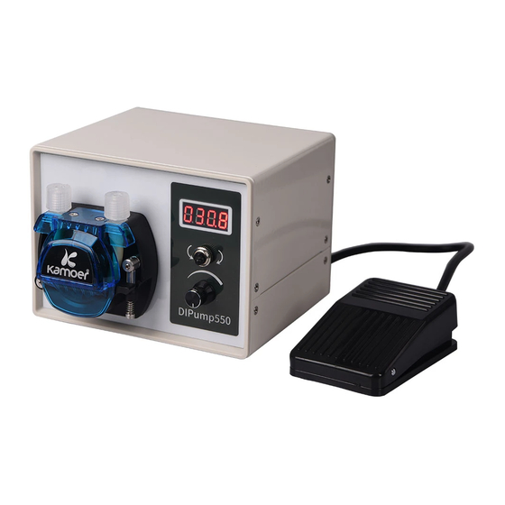
Page 4: Appearance Description
Appearance description Digital display Used to display information such as speed, flow and time; When all are numbers: the current speed/currently set speed; When all are numbers and all numbers are beating: The number indicates the currently set operating flow When the first digit is displayed and is beating: the last three digits indicate the currently set working time... - Page 5 Rotary encoder Used to adjust the speed and time; increase clockwise and decrease counterclockwise. The faster the rotation speed, the larger the increment of adjustment; The speed can be adjusted during the operation of the peristaltic pump. Direction control switch ...
- Page 6 Working mode setting—Speed Mode Fully automatic cycle mode setting 1. Press and hold the encoder in the speed setting state, the digital tube switches to the time setting mode, the first upper port jumps (red in the figure), at this time is set the running time of the pump;...
- Page 7 Working mode setting—Flow Mode Fully automatic cycle mode setting 1. In the flow mode, long press the encoder to switch to the operating flow setting. The nixie tube displays all numbers and flickers. At this time, it is to set the operating flow of the pump;...
- Page 8 Enter menu settings page 1. On the operation preparation page, long press the rotary encoder to switch to the working mode setting interface (If the operation mode is speed mode , The first digit of the nixie tube jumps (Red in the picture ); If the operation mode is flow mode, the digital display on the nixie tube is all digital, and it jumps and flashes ).
- Page 9 “C002” Direction adjustment In the function selection interface, the rotary encoder, when it displays "C002", the corresponding function is "direction level mode setting", short press the rotary encoder to enter the setting interface, and you can set the direction level mode. The last digit represents the direction level, which can be used to match the direction of the direction button and the label on the surface.
- Page 10 Interface Setting Introduce Edge trigger (press the foot switch once, the pump starts to work, press again, the pump stops) Low level trigger (long press the foot switch, pump work, release the foot switch, pump stop) High level trigger (releasing the foot switch, the pump works, long press the foot switch, the pump stops working)
- Page 11 “C005” Running status setting In the function selection interface, for the rotary encoder, when the corresponding function of "C005" is displayed as "saving in running state", short press the rotary encoder to enter the setting interface, and you can set whether to save the current running state.
- Page 12 fourth digits of the interface. At this time, turn the encoder to adjust the speed of suction (0.1-999.9ml/min). Interface Setting Introduce Suck back time Suction speed “C008” Drive enable In the function selection interface, for the rotary encoder, when the corresponding function of "C008"...
-
Page 13: External Control
External control 485 mode The board is controlled by 485 communication mode; please connect to the 485-communication wire. Analog signal control mode Control the board by analog signal mode (0~5V, 4~20mA); Please connect the signal line according to the actual control mode. Pin 1: reserved Pin 2: 485 B Pin 3: 485 A... - Page 14 Pump tube flow reference Pump pipe ID x OD Number Maximum flow Code material of rotors ml/min B146 1.6×4.8 B163 3.2×6.4 B403 4.0×7.2 B253 4.8×8.0 Note: the maximum flow in the above chart is obtained by testing water at 400 rpm with a new pump pipe aged for 30 minutes at room temperature (about 25 ℃) for reference only.
- Page 16 Kamoer Fluid Tech (Shanghai) Co., Ltd. Add: 4th Building, No 49 Xiangjing Road, Songjiang District, Shanghai, China Phone: +86-021-67742578 Fax: +86-021-67741776 Website: www.kamoer.com...
Need help?
Do you have a question about the DIPump550 and is the answer not in the manual?
Questions and answers