
Related Manuals for SATO KEIRYOKI Jumbo SK-1120


Summary of Contents for SATO KEIRYOKI Jumbo SK-1120
- Page 1 Instruction Manual Jumbo LCD Digital Thermometer Model SK-1120 (2-channel) 3-4, Kanda-kajicho, Chiyoda-ku, Tokyo 101-0045 Japan URL: http://www.sksato.co.jp/english M.11...
- Page 3 Thank you for purchasing the SK-1120 Jumbo LCD Digital Thermometer. - This product is designed to measure temperature. Do not use it for other purposes. - Read this manual thoroughly before using the digital thermometer. Keep the manual in a safe place for future references whenever necessary.
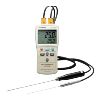
- Page 4 Overview The SK-1120 is handy type digital thermometer with 2 channels to measure temperature with connected K type thermocouple sensor probes. Jumbo LCD display makes easier to read temperature values. Features - Large LCD for easy reading The temperature is indicated on a large liquid crystal display (LCD). The seven-segment characters on the large LCD (upper display) are as high as 18 mm for easy reading.
- Page 5 2. Names and Functions of Components 2.1 Main unit Front View Rear View Upper View ① Display section The temperature reading and characters that indicates the current state of settings are displayed. ② POWER key Press this key to turn the main unit on (measurement mode). - Press this key again to turn off. ③...
- Page 6 ⑧ Sensor switch key : Displays, when pressed, the temperatures (T1 and T2) measured via the two probes, and their difference (T1 - T2) in sequence. ⑨ Battery cover : Six "AAA" size batteries are installed in the battery compartment. ⑩...
- Page 7 : Lights wn the offset (REL) display function is active. MX : Lights when the highest temperature (maximum value) is displayed. MN : Lights when the lowest temperature (minimum value) is displayed. AVG: Lights when the average temperature (average value) is displayed. Time display Displays the time elapsed since the TIME key was pressed.
- Page 8 4. Installing and replacing the batteries (1) Turn the setscrew on the battery cover counterclockwise with a flat-head screwdriver or a coin to remove it. Flip up the stand and remove the battery cover. (2) In case of replacement, remove all six old batteries.
- Page 9 6. Measurements (1) Connect the sensor probe(s) with a type "K" thermocouple connector to the main unit. Fully insert plug Align the positive (+) and negative (-) sides of the plug of the sensor probe with those of the connector receptacle on the main unit. The sensor probe SK-K010 provided as a standard accessory is designed to measure a temperature within the range of -50°C to 300°C.
- Page 10 7. Indication hold function Pressing the HOLD key, (H), holds the indication. This is useful for easy reading when the indication changes rapidly during measurements. Pressing the HOLD key again will release the indication hold function. 8. Maximum or minimum value display function The SK-1120 can display the highest temperature (maximum value) or the lowest temperature (minimum value) measured after the MAX/MIN key is pressed.
- Page 11 9. Average display function The SK-1120 can display the average temperature (AVG). The unit displays the average temperature measured (for up to approximately 9 hours) after the MAX/MIN key is pressed. These values are obtained by summation averaging. 10. Resolution switching function The resolution is automatically switched according to the temperature.
-
Page 12: Error Message
CAUTION Be sure to use the sensor probe with a type K thermocouple connector. Also, make sure the sensor probes to be connected to connectors 1 and 2 on the main unit are of the same type and have the same property. 13. -
Page 13: Troubleshooting
16. Troubleshooting Some of the following phenomena may not be considered defective. Check the phenomena carefully before requesting repair. Abnormal Possible cause(s) Action(s) to be taken phenomenon The batteries have run out. Replace with new batteries. If the power will not turn on If the parts have been damaged, ask even after properly inserting your Sato sales representative or our... -
Page 14: Specifications
The indication is The sensor probe connector is Fully insert the sensor probe connector. unstable (continued) not fully inserted. The sensor is not fully Review the sensor measurement contacting the object to be procedures. If the object's thermal measured. capacity is small, the indication may be affected by the protection tube size.
Need help?
Do you have a question about the Jumbo SK-1120 and is the answer not in the manual?
Questions and answers