Table of Contents
Advertisement
Quick Links
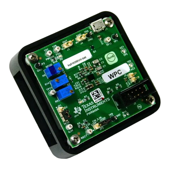
The bq51025EVM-649 (PWR649) wireless power receiver evaluation kit (EVM) from TI is a high
performance, easy-to-use development kit for the design of wireless power solutions. It helps designers
evaluate the operation and performance of the bq51025 IC, a secondary-side receiver device for wireless
power transfer applications. The bq51025 device is a fully-contained, wireless power receiver capable of
operating in WPC v1.1 protocol which allows a wireless power system to deliver up to 5 W to the system
when used with a Qi inductive transmitter. When paired with the bq500215EVM-648 (PWR648), the
bq51025 is capable of delivering up to 10 W to the system. The bq51025 device provides a single device
power conversion (rectification and regulation) as well as the digital control and communication for WPC
specification. The kit enables designers to speed up the development of their end-applications.
...................................................................................................................
1
2
3
4
5
5.1
5.2
5.3
5.4
5.5
5.6
5.7
6
6.1
6.2
.................................................................................................................
7
7.1
7.2
7.3
7.4
7.5
7.6
8
8.1
8.2
8.3
8.4
8.5
1
2
3
4
5
1.4-A Load Step
bq51025 Evaluation Module (PWR649)
..............................................................................................
..................................................................................................................
.....................................................................................
.................................................................................................
............................................................................................................
..................................................................................
....................................................................................................
............................................................................................
.............................................................................................
............................................................................................
..........................................................................................
.............................................................................................................
............................................................................................................
..........................................................................................................
..........................................................................................................
.............................................................................................................
.....................................................................................................
.................................................................................
.............................................................................................
................................................................................................
..................................................................................................
.................................................................................................
........................................................................................
............................................................................................
..............................................................................................
.....................................................................................
..............................................................................................................
...........................................................................................................
Copyright © 2014, Texas Instruments Incorporated
..........................................................
.........................................................................
....................................................................
User's Guide
SLUUB55 - September 2014
2
3
4
4
5
5
6
6
7
7
8
9
10
10
10
14
14
15
16
17
17
18
19
19
19
19
21
24
5
11
14
15
15
1
Advertisement
Table of Contents

Related Manuals for Texas Instruments bq51025EVM-649


Summary of Contents for Texas Instruments bq51025EVM-649
-
Page 1: Table Of Contents
SLUUB55 – September 2014 bq51025 Evaluation Module (PWR649) The bq51025EVM-649 (PWR649) wireless power receiver evaluation kit (EVM) from TI is a high performance, easy-to-use development kit for the design of wireless power solutions. It helps designers evaluate the operation and performance of the bq51025 IC, a secondary-side receiver device for wireless power transfer applications. -
Page 2: Contents 1 Introduction
10 W. The bq51025 incorporates a proprietary two-way authentication with the bq500215 primary controller that allows optimal power transfer and system performance up to 10-W output power. bq51025 Evaluation Module (PWR649) SLUUB55 – September 2014 Submit Documentation Feedback Copyright © 2014, Texas Instruments Incorporated... -
Page 3: Considerations With This Evm
Considerations with this EVM The bq51025EVM-649 evaluation module (PWR649) demonstrates the receiver portion of the wireless power system. This receiver EVM is a complete receiver-side solution that produces 10-W output power at up to 2-A load with adjustable output voltage. The 10-W output power can be delivered from various output voltages. -
Page 4: Modifications
(C1, C2, and C3). Thermal performance of these capacitors can greatly impact overall system performance. Recommended Operating Conditions Table 1 provides a summary of the bq51025EVM-649 performance specifications. All specifications are given for an ambient temperature of 25°C. Table 1. bq51025EVM-649 Recommended Operating Conditions PARAMETER... -
Page 5: Equipment And Evm Setup
Number: PWR649 Rev: Sheet Title: Texas Instruments and/or its licensors do not warra nt the accuracy or completeness of this specificati on or any information contained therein. Texas Inst ruments and/or its licensors do not SVN Rev: Not in version control... -
Page 6: Recommended Test Equipment
Connect the ammeter to measure PS #1 (12-V input) current to the PWR648. Connect the voltmeter to monitor the input voltage at J1 and J2 of PWR648 unit. bq51025 Evaluation Module (PWR649) SLUUB55 – September 2014 Submit Documentation Feedback Copyright © 2014, Texas Instruments Incorporated... -
Page 7: Connector Descriptions
Connector Descriptions The connections points are described in the following paragraphs. 5.4.1 J1 – AD External Adapter Input Power can be provided to simulate an external adapter applied to the receiver in this bq51025EVM-649 (PWR649). 5.4.2 J2 – Programming Connector This connector is populated and can be used for I C communication using the USB-TO-GPIO "HPA172"... -
Page 8: Test Point Descriptions
Allows individual trimming of R5 and R14 for optimum power delivery for 5-W and 10-W systems. 5.6.8 TP12– Input Power Connected to J1 pin 1. Alternative connection for wired power. bq51025 Evaluation Module (PWR649) SLUUB55 – September 2014 Submit Documentation Feedback Copyright © 2014, Texas Instruments Incorporated... -
Page 9: Pin Description Of The Ic
C2, C3, C4, C5 RECT BOOT2 D1, D2, D3, D4, D5, D6 CLAMP1 AD_EN VIREG CLAMP2 COMM1 PMODE COMM2 VO_REG ILIM CM_ILIM TS/CTRL TMEM PD_DET SLUUB55 – September 2014 bq51025 Evaluation Module (PWR649) Submit Documentation Feedback Copyright © 2014, Texas Instruments Incorporated... -
Page 10: Test Procedure
Test Procedure www.ti.com Test Procedure This procedure describes the test configuration of the bq51025EVM-649 evaluation board (PWR649) for bench evaluation. Definition The following naming conventions are used: VXXX : External voltage supply name (VBAT, VTS, V LOADW: External load name (LOADR, LOADI) V(TPyy): Voltage at internal test point TPyy. -
Page 11: Placement Of Pwr649 On Pwr648
Note that if the CM_ILIM jumper (JP2) is set to low, the efficiency will be negatively impacted • Remove UUT from the TX and turn OFF PS #1 SLUUB55 – September 2014 bq51025 Evaluation Module (PWR649) Submit Documentation Feedback Copyright © 2014, Texas Instruments Incorporated... - Page 12 • Initial adapter testing will be done without the transmitter • Connect 5 V ±250 mV adapter on J1 on the bq51025EVM-649 receiver (or use TP12 / PS #3 and GND) • Adjust the load current to 500 mA ±50 mA (J3 OUT and J4 GND) •...
- Page 13 PWR649 will begin to decrease towards 6.0 V (J3 to J4) indicating maximum power is reached • Remove UUT from the TX and turn OFF PS #2 SLUUB55 – September 2014 bq51025 Evaluation Module (PWR649) Submit Documentation Feedback Copyright © 2014, Texas Instruments Incorporated...
-
Page 14: Test Results
I (Battery) bq24261 P (4 V * 2.1 A) ~8.4 W bq24261 V (Battery) Figure 3. bq51025 in Steady State Operation with bq24261 bq51025 Evaluation Module (PWR649) SLUUB55 – September 2014 Submit Documentation Feedback Copyright © 2014, Texas Instruments Incorporated... -
Page 15: Load Step
5. Note that this step requires more time to recover to the full output voltage. RECT IOUT Figure 4. 1-A Load Step RECT IOUT Figure 5. 1.4-A Load Step SLUUB55 – September 2014 bq51025 Evaluation Module (PWR649) Submit Documentation Feedback Copyright © 2014, Texas Instruments Incorporated... -
Page 16: Start Up
Starting up with a 5 Ω at J3 to J4 generates a 1.4-A load and is shown in Figure 7 IOUT RECT Figure 6. Start Up With 1000 mA IOUT RECT Figure 7. Start Up With 1400 mA bq51025 Evaluation Module (PWR649) SLUUB55 – September 2014 Submit Documentation Feedback Copyright © 2014, Texas Instruments Incorporated... -
Page 17: Efficiency Data
Figure 9 illustrates the behavior of the bq51025EVM-649 when an adapter is inserted into J1 (or at TP12) while the EVM is on the transmitter pad with a resistive load at J3 to J4. There is some off time during the transitions between wireless power and wired power modes. -
Page 18: Thermal Performance
Thermal Performance This section shows a thermal image of the bq51025EVM-649. A 1.4-A load is used and the output voltage is set to 7 V (approximately 10 W). There is no air flow and the ambient temperature is 25°C. The peak temperature of the device (41.4°C) is well below the maximum recommended operating condition listed in... -
Page 19: Layout And Bill Of Material
The primary concerns when laying a custom receiver PCB are as follows: • AC1 and AC2, GND return trace resistance • OUT trace resistance • GND connection • Copper weight ≥ 2 oz SLUUB55 – September 2014 bq51025 Evaluation Module (PWR649) Submit Documentation Feedback Copyright © 2014, Texas Instruments Incorporated... -
Page 20: Bq51025Evm-649 Layout Example
Via interconnects are placed close to RECT used to aid in thermal and OUT dissipation J use where possible Figure 11. bq51025EVM-649 Layout Example bq51025 Evaluation Module (PWR649) SLUUB55 – September 2014 Submit Documentation Feedback Copyright © 2014, Texas Instruments Incorporated... -
Page 21: Bq51025Evm-649 Layout
Layout and Bill of Material www.ti.com bq51025EVM-649 Layout Figure 12 through Figure 16 show the bq51025EVM-649 PCB layout. Figure 12. bq51025EVM-649 Top Assembly Figure 13. bq51025EVM-649 Layer 1 SLUUB55 – September 2014 bq51025 Evaluation Module (PWR649) Submit Documentation Feedback Copyright © 2014, Texas Instruments Incorporated... -
Page 22: Bq51025Evm-649 Layer
Layout and Bill of Material www.ti.com Figure 14. bq51025EVM-649 Layer 2 Figure 15. bq51025EVM-649 Layer 3 bq51025 Evaluation Module (PWR649) SLUUB55 – September 2014 Submit Documentation Feedback Copyright © 2014, Texas Instruments Incorporated... -
Page 23: Bq51025Evm-649 Layer
Layout and Bill of Material www.ti.com Figure 16. bq51025EVM-649 Layer 4 SLUUB55 – September 2014 bq51025 Evaluation Module (PWR649) Submit Documentation Feedback Copyright © 2014, Texas Instruments Incorporated... -
Page 24: Bill Of Materials (Bom)
Layout and Bill of Material www.ti.com Bill of Materials (BOM) Table 3 lists the BOM for the EVM. Table 3. bq51025EVM-649 Bill of Materials Designator Quantity Value Description PackageReference PartNumber Manufacturer !PCB Printed Circuit Board PWR649 0.047uF CAP, CERM, 0.047uF, 50V, +/-5%, C0G/NP0, 1206... - Page 25 Layout and Bill of Material www.ti.com Table 3. bq51025EVM-649 Bill of Materials (continued) Designator Quantity Value Description PackageReference PartNumber Manufacturer 102k RES, 102k ohm, 1%, 0.063W, 0402 0402 CRCW0402102KFKED Vishay-Dale RES, 237 ohm, 1%, 0.1W, 0603 0603 CRCW0603237RFKEA Vishay-Dale R5, R6, R14 500 Ohm Trimmer, 500 ohm, 0.25W, TH...
- Page 26 STANDARD TERMS AND CONDITIONS FOR EVALUATION MODULES Delivery: TI delivers TI evaluation boards, kits, or modules, including any accompanying demonstration software, components, or documentation (collectively, an “EVM” or “EVMs”) to the User (“User”) in accordance with the terms and conditions set forth herein. Acceptance of the EVM is expressly subject to the following terms and conditions.
- Page 27 FCC Interference Statement for Class B EVM devices NOTE: This equipment has been tested and found to comply with the limits for a Class B digital device, pursuant to part 15 of the FCC Rules. These limits are designed to provide reasonable protection against harmful interference in a residential installation.
- Page 28 【無線電波を送信する製品の開発キットをお使いになる際の注意事項】 本開発キットは技術基準適合証明を受けておりません。 本製品のご使用に際しては、電波法遵守のため、以下のいずれかの措置を取っていただく必要がありますのでご注意ください。 1. 電波法施行規則第6条第1項第1号に基づく平成18年3月28日総務省告示第173号で定められた電波暗室等の試験設備でご使用 いただく。 2. 実験局の免許を取得後ご使用いただく。 3. 技術基準適合証明を取得後ご使用いただく。 なお、本製品は、上記の「ご使用にあたっての注意」を譲渡先、移転先に通知しない限り、譲渡、移転できないものとします。 上記を遵守頂けない場合は、電波法の罰則が適用される可能性があることをご留意ください。 日本テキサス・インスツルメンツ株式会社 東京都新宿区西新宿6丁目24番1号 西新宿三井ビル 3.3.3 Notice for EVMs for Power Line Communication: Please see http://www.tij.co.jp/lsds/ti_ja/general/eStore/notice_02.page 電力線搬送波通信についての開発キットをお使いになる際の注意事項については、次のところをご覧くださ い。http://www.tij.co.jp/lsds/ti_ja/general/eStore/notice_02.page SPACER EVM Use Restrictions and Warnings: 4.1 EVMS ARE NOT FOR USE IN FUNCTIONAL SAFETY AND/OR SAFETY CRITICAL EVALUATIONS, INCLUDING BUT NOT LIMITED TO EVALUATIONS OF LIFE SUPPORT APPLICATIONS.
- Page 29 Notwithstanding the foregoing, any judgment may be enforced in any United States or foreign court, and TI may seek injunctive relief in any United States or foreign court. Mailing Address: Texas Instruments, Post Office Box 655303, Dallas, Texas 75265 Copyright © 2014, Texas Instruments Incorporated...
- Page 30 IMPORTANT NOTICE Texas Instruments Incorporated and its subsidiaries (TI) reserve the right to make corrections, enhancements, improvements and other changes to its semiconductor products and services per JESD46, latest issue, and to discontinue any product or service per JESD48, latest issue.
- Page 31 Mouser Electronics Authorized Distributor Click to View Pricing, Inventory, Delivery & Lifecycle Information: Texas Instruments BQ51025EVM-649...
Need help?
Do you have a question about the bq51025EVM-649 and is the answer not in the manual?
Questions and answers