Table of Contents
Advertisement
Quick Links
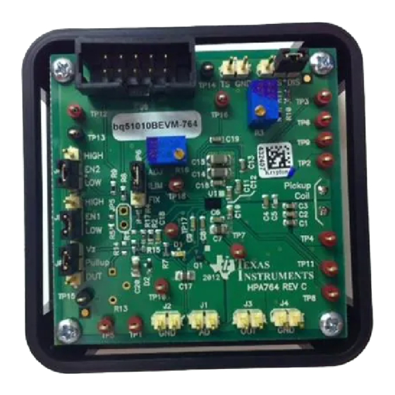
bq51010BEVM-764 Evaluation Module (WCSP Package)
The bq51010BEVM-764 (EVM) wireless power receiver evaluation kit from TI is a high-performance, easy-
to-use development kit for the design of wireless power solutions. The EVM helps designers to evaluate
the operation and performance of the bq51010B, 7-V power supply for wireless power transfer. The
bq51010B devices provide AC/DC power conversion and regulation while integrating the digital control
required to comply with the Qi-communication protocol. The kit speeds up the development of end-use
applications.
1
2
3
4
4.1
4.2
4.3
4.4
4.5
5
5.1
5.2
5.3
5.4
6
6.1
6.2
6.3
6.4
6.5
7
7.1
7.2
1
..................................................................................................................
2
3
4
....................................................................................................................
5
6
7
8
9
10
11
bqTESLA is a trademark of Texas Instruments, Inc..
SLUUAE3A - August 2013 - Revised December 2013
Submit Documentation Feedback
.............................................................................................
.................................................................................................................
.....................................................................................
................................................................................................
...........................................................................................................
............................................................................................
............................................................................................
..........................................................................................
..............................................................................................................
............................................................................................................
.................................................................................
...................................................................................................
...........................................................................................................
................................................................................................................
..........................................................................................................
........................................................................................................
............................................................................................................
..........................................................................................................
............................................................................................
................................................................................................
..............................................................................................................
...........................................................................................
.........................................................................................................
.............................................................................................
...........................................................................................
...............................................................................
OUT
.............................................................................................................
..................................................................................
.....................................................................................
..........................................................................................
Copyright © 2013, Texas Instruments Incorporated
SLUUAE3A - August 2013 - Revised December 2013
.........................................................................
List of Figures
............................................................................
bq51010BEVM-764 Evaluation Module (WCSP Package)
User's Guide
2
2
2
3
3
3
3
4
5
6
6
6
7
8
10
10
10
11
12
12
14
14
17
3
7
10
11
12
12
13
14
15
15
16
1
Advertisement
Table of Contents

Related Manuals for Texas Instruments bq51010BEVM-764


Summary of Contents for Texas Instruments bq51010BEVM-764
-
Page 1: Table Of Contents
SLUUAE3A – August 2013 – Revised December 2013 bq51010BEVM-764 Evaluation Module (WCSP Package) The bq51010BEVM-764 (EVM) wireless power receiver evaluation kit from TI is a high-performance, easy- to-use development kit for the design of wireless power solutions. The EVM helps designers to evaluate the operation and performance of the bq51010B, 7-V power supply for wireless power transfer. -
Page 2: Contents 1 Considerations With This Evm
Bill of Materials Considerations with this EVM The bq51010BEVM-764 evaluation module (HPA764-005) demonstrates the receiver portion of the bqTESLA™ wireless power system. This receiver EVM is a complete receiver-side solution that produces 7-V output at up to a 720-mA load (5 W). -
Page 3: Equipment And Evm Setup
This connector is populated and is only useful at the factory level for programming the IC. Jumpers and Switches The control jumpers are described in the following paragraphs. SLUUAE3A – August 2013 – Revised December 2013 bq51010BEVM-764 Evaluation Module (WCSP Package) Submit Documentation Feedback Copyright © 2013, Texas Instruments Incorporated... -
Page 4: Test Point Descriptions
Overvoltage clamp drive signal, open-drain output is connected to OVP capacitor. 4.4.7 TP7 – OUT Output Voltage This test point is the output voltage. bq51010BEVM-764 Evaluation Module (WCSP Package) SLUUAE3A – August 2013 – Revised December 2013 Submit Documentation Feedback Copyright © 2013, Texas Instruments Incorporated... -
Page 5: Pin Description Of The Ic
B3, B4 AC1, AC1 BOOT2 C2, C3 RECT BOOT1 D1, D2, D3, D4 COM2 CLMP2 CLMP1 COM1 TS/CTRL AD-EN SLUUAE3A – August 2013 – Revised December 2013 bq51010BEVM-764 Evaluation Module (WCSP Package) Submit Documentation Feedback Copyright © 2013, Texas Instruments Incorporated... -
Page 6: Test Procedure
Two DC voltmeters and two DC ammeters are required. 5.2.4 bqTesla Transmitter The transmitter HPA689 or equivalent is used for final test. bq51010BEVM-764 Evaluation Module (WCSP Package) SLUUAE3A – August 2013 – Revised December 2013 Submit Documentation Feedback Copyright © 2013, Texas Instruments Incorporated... -
Page 7: Equipment Setup
Connect ohm meter between JP6 ADJ and J2 (GND). Adjust R16 to 415 Ω, ±20-Ω reading on the ohmmeter. SLUUAE3A – August 2013 – Revised December 2013 bq51010BEVM-764 Evaluation Module (WCSP Package) Submit Documentation Feedback Copyright © 2013, Texas Instruments Incorporated... -
Page 8: Procedure
UUT: Verify that the rectified voltage should be 7.5 V to 7.05 V (between TP12 and TP13) (Note: a modulation signal is present on this voltage every 250 ms and may cause fluctuation in the reading, use lower value or base line) bq51010BEVM-764 Evaluation Module (WCSP Package) SLUUAE3A – August 2013 – Revised December 2013 Submit Documentation Feedback... - Page 9 Verify that: 1. UUT: TP7 V is 6.5 V to 7.1 V 2. Transmitter: Status LED D5 is off SLUUAE3A – August 2013 – Revised December 2013 bq51010BEVM-764 Evaluation Module (WCSP Package) Submit Documentation Feedback Copyright © 2013, Texas Instruments Incorporated...
-
Page 10: Test Results
Provide a load dump from 14 Ω or 500 mA (if using a current source load) to no load (high impedance). • Monitor load current, rectifier voltage, and output voltage as shown in Figure bq51010BEVM-764 Evaluation Module (WCSP Package) SLUUAE3A – August 2013 – Revised December 2013 Submit Documentation Feedback Copyright © 2013, Texas Instruments Incorporated... -
Page 11: Start-Up
Set up the test bench as described in Section • Power TX with 19 V • Trigger scope sweep on TP2 AC IN SLUUAE3A – August 2013 – Revised December 2013 bq51010BEVM-764 Evaluation Module (WCSP Package) Submit Documentation Feedback Copyright © 2013, Texas Instruments Incorporated... -
Page 12: Efficiency
Thermal Performance This section shows a thermal image of the bq51010BEVM-764. A 7.0-V output is used at a 720-mA load. There is no air flow and the ambient temperature is 25°C. The peak temperature of the IC, 44.9°C, is well below the maximum recommended operating condition listed in the data sheet. -
Page 13: Thermal Image
Test Results www.ti.com Figure 7. Thermal Image SLUUAE3A – August 2013 – Revised December 2013 bq51010BEVM-764 Evaluation Module (WCSP Package) Submit Documentation Feedback Copyright © 2013, Texas Instruments Incorporated... -
Page 14: Layout And Bill Of Material
It is always a good practice to place high-frequency bypass capacitors of 0.1 μF next to RECT and OUT. Figure 8 illustrates an example of a WCSP layout: Figure 8. bq51010BEVM-764 Layout Example bq51010BEVM-764 Evaluation Module (WCSP Package) SLUUAE3A – August 2013 – Revised December 2013 Submit Documentation Feedback Copyright ©... -
Page 15: Bq51010Bevm-764 Top Assembly
Layout and Bill of Material www.ti.com 7.1.2 Layout Figure 9. bq51010BEVM-764 Top Assembly Figure 10. bq51010BEVM-764 Top Layer SLUUAE3A – August 2013 – Revised December 2013 bq51010BEVM-764 Evaluation Module (WCSP Package) Submit Documentation Feedback Copyright © 2013, Texas Instruments Incorporated... -
Page 16: Bq51010Bevm-764 Bottom Copper Layer
Layout and Bill of Material www.ti.com Figure 11. bq51010BEVM-764 Bottom Copper Layer Figure 12. bq51010BEVM-764 Bottom Assembly bq51010BEVM-764 Evaluation Module (WCSP Package) SLUUAE3A – August 2013 – Revised December 2013 Submit Documentation Feedback Copyright © 2013, Texas Instruments Incorporated... -
Page 17: Bill Of Materials (Bom)
Layout and Bill of Material www.ti.com Bill of Materials (BOM) Table 3. bq51010BEVM-764 Bill of Materials COUNT RefDes Value Description Size Part Number 68nF Capacitor, Ceramic, 50V, X7R, 10% 0603 68nF Capacitor, Ceramic, 50V, X7R, 10% 0603 12nF Capacitor, Ceramic, 50V, X7R, 10%... - Page 18 Layout and Bill of Material www.ti.com Table 3. bq51010BEVM-764 Bill of Materials (continued) COUNT RefDes Value Description Size Part Number Potentiometer, 1/4 in. Cermet, 12-Turn, Top-Adjust 0.25x0.17 3266W-1-502LF Bourns Resistor, Chip, 1/16W, 1% 0603 42.2K Resistor, Chip, 1/16W, 1% 0603...
- Page 19 Layout and Bill of Material www.ti.com Table 3. bq51010BEVM-764 Bill of Materials (continued) COUNT RefDes Value Description Size Part Number HPA764-004 bq51051BEVM-764 HPA764-005 bq51010BEVM-764 SLUUAE3A – August 2013 – Revised December 2013 bq51010BEVM-764 Evaluation Module (WCSP Package) Submit Documentation Feedback...
- Page 20 Added Wyurth part 760308103204, in 'Coil, RX with Attractor' row of BOM. NOTE: Page numbers for previous revisions may differ from page numbers in the current version. Revision History SLUUAE3A – August 2013 – Revised December 2013 Submit Documentation Feedback Copyright © 2013, Texas Instruments Incorporated...
- Page 21 Any exceptions to this are strictly prohibited and unauthorized by Texas Instruments unless user has obtained appropriate experimental/development licenses from local regulatory authorities, which is responsibility of user including its acceptable authorization.
- Page 22 FCC Interference Statement for Class B EVM devices This equipment has been tested and found to comply with the limits for a Class B digital device, pursuant to part 15 of the FCC Rules. These limits are designed to provide reasonable protection against harmful interference in a residential installation. This equipment generates, uses and can radiate radio frequency energy and, if not installed and used in accordance with the instructions, may cause harmful interference to radio communications.
- Page 23 Also, please do not transfer this product, unless you give the same notice above to the transferee. Please note that if you could not follow the instructions above, you will be subject to penalties of Radio Law of Japan. Texas Instruments Japan Limited (address) 24-1, Nishi-Shinjuku 6 chome, Shinjuku-ku, Tokyo, Japan http://www.tij.co.jp...
- Page 24 FDA Class III or similar classification, then you must specifically notify TI of such intent and enter into a separate Assurance and Indemnity Agreement. Mailing Address: Texas Instruments, Post Office Box 655303, Dallas, Texas 75265 Copyright © 2013, Texas Instruments Incorporated...
- Page 25 IMPORTANT NOTICE Texas Instruments Incorporated and its subsidiaries (TI) reserve the right to make corrections, enhancements, improvements and other changes to its semiconductor products and services per JESD46, latest issue, and to discontinue any product or service per JESD48, latest issue.
- Page 26 Mouser Electronics Authorized Distributor Click to View Pricing, Inventory, Delivery & Lifecycle Information: Texas Instruments BQ51010BEVM-764...
Need help?
Do you have a question about the bq51010BEVM-764 and is the answer not in the manual?
Questions and answers