Table of Contents

Related Manuals for icetro ISI-271SHSN


Summary of Contents for icetro ISI-271SHSN
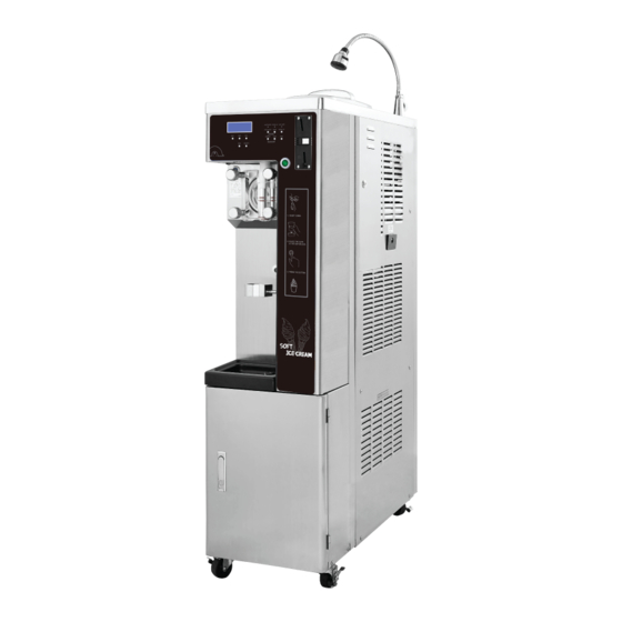
- Page 1 SOFT ICE CREAM SELF MACHINE User s Manual ISI-271SHSN LOCK This product is designed for indoor use . ● Make sure to install it indoors. ● ● The appearance, design, color, and parts of the product are subject to change without prior notice.
- Page 2 Soft ice cream Self machine offers the following advantages 1. Minimum noise and refreshing cooling system With a high efficiency and low noise motor, we can achieve minimal noise from the refreshing cooling system 2. MICOM control method Use of an artificial intelligence control type achieves an optimal cooling system. 3.
-
Page 3: Table Of Contents
Dear customers Thank you very much for purchasing a soft ice cream self machine made by ICETRO. For correct use of the product and its maintenance, please read this manual carefully. If a problem occurs while using the product, you can refer to this manual for troubleshooting. This manual contains a product warranty, so keep it safely for future reference. -
Page 4: Cautions For Your Safety
Cautions for your safety Note: Original instructions is provided by ICETRO Co., Ltd. The caution/warning details for safety are intended to prevent accident or danger through safe and proper use. Therefore please follow the details accordingly. The precaution details are categorized into warning and caution, and the respective meanings are as follows. - Page 5 Cautions for your safety For relocation of the product, call an expert. Keep your warning and caution The product may cause such hazards as labels clean for easy legibility. Label falling down unless properly installed. If the user misunderstands Warning It should be installed in accordance with related the content of such a label, regulations such as KS standards, the road and...
- Page 6 Caution handing or operation. Caution Note: Translations of the original instructions is provied by ICETRO co., Ltd. While operating the product, please close the upper cap completely. Do not arbitrarily connect Bugs or alien substances the power cord or process can enterthe product.
- Page 7 Cautions for your safety If the supply cord is damaged, it must be replaced by the manufacture, Do not inject inflammable its service agent or similarly qualitied material such as benzene, persons in order to avoid a harzard. gasoline, paint thinner or LP gas into the product Fire or electric shock may occur.
- Page 8 Cautions for your safety Do not touch the power cable or any elctric part with wet Please do not press “WASH” button during empty condition which the hands. cylinder doesn’t contain any Explosion, fire or injury may ingredients or water. occur.
- Page 9 Cautions for your safety The instructions for appliances connected to the water mains This appliance is not by detachable hose-sets intended for use by persons shall state that (including children) the new hose-sets with reduced physical, supplied with the appliance sensory or mental are to be used and that capabilities, or lack of...
-
Page 10: Unpacking And Installation Method
Unpacking and Installation method The Soft Ice Cream Self Machine has been fully inspected and tested at the factory prior to shipping. If you detect damage to the wooden package or apparent distortion of the shape of the system after unpacking the product, immediately inform your distributor or manufacturer. Find the serial number marked on the packing and the machine before starting installation. -
Page 11: How To Install
How to install How to install! ● The raw water supply valve may vary depending on the installation environment of the system. - Consult with the engineers of the company for the details of installation of the system to ensure optimal performance of the system (change of the installation site of the system also requires consultation with the engineer of the company). -
Page 12: Name Of Each Part
Name of each part Front view Back view WATER VALVE COVER BASKET TOP COVER WINDOW CONTROL BUTTON WASH BUTTON SELECT POWER SWITCH BUTTON DASHER COVER PUSH DASHER COVER BUTTON BOLT CUP SENSOR FEEDER DRAIN BOX CONDENSER LOCK FILTER LOCK RAW STORES FOOT... - Page 13 Name of each part Left view FRONT COVER UP FEEDER ROAD SIDE PANEL L Note: For buyer request, it can be movable designed. (Caster or leg) Right view FEEDER COVER DRAIN SLUG SIDE PANEL R CASTER...
- Page 14 Name of each part Parts BRUSH DRUM DASHER LUG FRONT WHITE 1 EA 1 EA MANUAL 1 EA DASHER LUG BACK WHITE 1 EA BRUSH COVER PACKING DASHER COVER 1 EA 1 EA SHAFT POM PACKING HINES 2 EA 1 EA BRUSH CARBURETOR IN 1 EA CABURATOR PACKING...
-
Page 15: Product Specification
Product specification CLASSIFICATION SPECIFICATION Product name SOFT ICE CREAM SELF MACHINE Model name ISI - 271SHSN Rated voltage and frequency 1 Φ , 220 V, 60 Hz 1 Φ , 230 V, 50 Hz Power consumption 15 A, 2200 W 19 A, 2560 W WIDTH 380 mm... -
Page 16: Check Prior To Use
Check prior to use Make sure to check them prior to use 【 】 Do not block the air vent. ● The air suction and discharge should be facilitated so that the cooling performance can be optimized. Periodic filter cleaning ●... -
Page 17: Button Display Names And Functions
Button display names and functions DISPLAY WINDOW ‘ ’ ●Displays the degree of soft ice cream formation in operation. [ A u t o ] I c e c r e a m L e v e l 6 0 % / 6 0 % [ A ] M i d d l e... -
Page 18: Functional Description Of The Buttons
Functional description of the buttons Detail description of each mode 【 】 Pour the raw material in the mixing tank and press the Making soft ice cream in ‘AUTO’ mode. ‘AUTO’ button. The following status display will be shown. Current level of soft ice cream is indicated. ①... - Page 19 Functional description of the buttons Detail description of each mode 【 】 If the soft ice cream is not used for a long time, then its shape ‘ ’ Regeneration mode. will be degraded. In this case, you can use the ‘Regeneration’ function to make it look better.
- Page 20 Functional description of the buttons [ Detailed description of each mode ] ‘PASTEURIZE’ Mode If pasteurization is not done every day, and the ingredients [ H e a t ] H o p p e r T e m p 3 0 / 3 0 : 56 .
- Page 21 Functional description of the buttons [ Check the setting ] ress the ‘ ’ button lightly to enter the mode where set-up value can be confirmed, as shown below. In the confirmation mode, Press the ‘ ’ button to SE T see the setting values in the following order.
- Page 22 Functional description of the buttons [ Check the record ] Press the ‘ ’ button for three seconds to check the SELECT records in the order of Sterilization, Washing, and Error, as shown in the right. Display items can be changed with the ‘DEC.’, ‘INC.’...
-
Page 23: Explanation Of The Function Button
Explanation of the function button Change the setting 【 】 Press the ‘SET’ button for three seconds to enter the setting change mode as follows. Move to other items using the ‘DEC.’ and ‘INC.’ buttons. Press the ‘SET’ button. While the setting value is flashing, change the value using the ‘DEC.’... - Page 24 Explanation of the function button After set the ‘3-10-6’ . It sets the dispensing amount of the ice cream. 3-8-1: Set the detailed category for the ‘4 ’ ejection [ 3 - 8 ] S a l e W e i g h t amounts from Category ‘3- 7 ’...
- Page 25 Explanation of the function button Item applied after setting the items in 3-10-6; the function sets the discharge quantity of ice cream 1. After putting in the ingredient and pressed ‘AUTO’ . 2. When pushed ‘AUTO’ + ‘DEFROST’ button during operation. 3.
-
Page 26: Category
⑦ ⑧ ⑨ ⑩ ⑪ ⑫ ⑬ ① Icetro ⑦ 1 : Number of discharge ports ② S : Soft (1: 1EA, 3: 3EA) ⑧ T : T - Table type ③ I : Icecream ④ S : S - Self machine... - Page 27 Explanation of the function buttons (set by an Administrator) 4-1: Rest time setting [ 4 - 1 ] B r e a k T i m e This is the function to allow the compressor to rest for a C y l i n d e r ( A U T O ) certain period of time by minute after the soft ice cream 8 .
- Page 28 Explanation of the function buttons (set by an Administrator) 4-7: 1 rise level calculation ℃ When the soft ice cream is made, 100% is displayed on the [ 4 - 7 ] L e v e l C a l c u l a t e LCD window and the percentage value is deducted from the ( A U T O ) compressor rest time.
- Page 29 Explanation of the function buttons (set by an Administrator) 4-9-7: Selection of auto pasteurization [ 4 - 9 ] H e a t i n g Choose ON for auto pasteurization and choose OFF for 7 . A ut o H e a t no auto pasteurization.
- Page 30 Explanation of the function buttons (set by an Administrator) 4-12: No load detection function setting [ 4 - 1 2 ] C u r r e n t S e t The no load detection function can be turned ON/OFF. : O n ‘...
- Page 31 Explanation of the function buttons (set by an Administrator) 4-18/4-81-1: Select the use of refresh. [ 4 - 1 8 ] R e f r e s h 1 . W o r k i n g ? 4-18-2: Refresh time setting 2 .
- Page 32 Explanation of the function buttons (set by an Administrator) 4-24/4-24-1: Wash detection function setting [ 4 - 2 4 ] S e n s i n g This is the category to select the wash detection C l e a n i n g function.
- Page 33 Explanation of the function buttons (set by an Administrator) 4-26: Hopper temperature compensation function setting The temperature in the hopper is measured with the temperature sensor on the floor of the hopper. The temperature is correct in the models having an impeller, however it may have deviation in the models without impeller.
- Page 34 Explanation of the function buttons (set by an Administrator) 4-29-2: Heating temperature setting during water boiling [ 4 - 2 9 ] B o i l i n g It sets the temperature of raw material in 1 . W o r k i n g ? the cylinder and hopper during water boiling.
- Page 35 Explanation of the function buttons (set by an Administrator) 4-33/4-33-1: Auto recycling function setting [ 4 - 3 3 ] A u t o Activate this category when auto recycling is needed. R e g e n e r a t i o n Make sure to block the carburetor hole when 1 .
- Page 36 Explanation of the function buttons (set by an Administrator) 4-36: Auto selection(It applies to the fully automatic vending [ 4 - 3 6 ] A u t o R e s t a r t machine, not to the manual system.) This selects the function to set standby when the category O f f ‘4-35-1’...
- Page 37 Explanation of the function buttons (set by an Administrator) 4-38-1: Select whether to use ‘ Standby’ button [ 4 - 3 8 ] S t a n d b y When this category is activated, press the ‘ refresh’ 1 . B u t t o n U s e button for longer than 3 seconds to operate the 2 .
- Page 38 Explanation of the function buttons (set by an Administrator) 4-39/4-39-1: Refrigeration valve operation selection [ 4 - 3 9 ] W o r k It selects the use of operation time of refrigeration valve R e f . V a l v e that refrigerate the raw material in the hopper.
-
Page 39: Explanation Of The Function Buttons
Explanation of the function buttons(set by a user) Only experts that have been designated by the main office or by those who received professional education and received approval from the main office shall adjust this category. A service charge will be applied if problems occur due to unapproved alterations. Press ‘DEC.’... - Page 40 Explanation of the function buttons(set by a user) 9-4-2: Refrigeration valve operation time setting It sets the operation time of refrigeration valve that refrigerates the raw material in the hopper. Be careful as ice can be formed on the wall of the hopper when the time of this category is adjusted too much.
- Page 41 Explanation of the function buttons(set by a user) 9-7-3: Set up the time criteria for deciding ‘ LOW’ [ 9 - 7 ] " L O W " in resale Set up the reference time for deciding F u n c t i o n ‘...
- Page 42 Explanation of the function buttons(set by a user) 9-9-5: Second Hot gas valve operating time set up [ 9 - 9 ] H e a t i n g Set up the valve operating time after the cycle operation a f t e r F r e e z e r H o t g a s of ‘...
- Page 43 Explanation of the function buttons(set by a user) 9-15-1: Current compensation value in case of no sale during operation [ 9 - 1 5 ] C o r r e c t ( L e f t When soft ice cream is not sold for a long period of time, S e t t i n g C u r r e n t it becomes thin and ejection amount tends to be large.
-
Page 44: How To Check The Operation Of Each Part
Explanation of the function buttons(set by a user) 9-18: Time Adjust brightness of LCD BACK LIGHT [ 9 - 1 8 ] L C D B a c k L i g h t Adjust the LCD BACK LIGHT time 1 . -
Page 45: Sale Related Settings
Sale related Settings If you push ‘ CHK’ and ‘ SELECT’ button at the same time for 2 seconds, you enter into sales related settings, and you can change relevant values by pressing ‘ SET’ button. 1-1: Verifying the total sales amount. 1-2: Verifying the total sales quantity. - Page 46 Sale related Settings 1-3: Verifying the total sales amount for cash 1-4: Verifying the total sales quantity for cash [ 1 - 4 ] T o t a l C a s h C o u n t [ 1 - 3 ] T o t a l C a s h S u m T o t a l : T o t a l : $...
- Page 47 Sale related Settings 1-5: Verifying the total sales amount for card 1-6: Verifying the total sales quantity for card [ 1 - 6 ] T o t a l C a r d C o u n t [ 1 - 5 ] T o t a l C a r d S u m T o t a l : T o t a l : $...
- Page 48 Sale related Settings 1-6: Setting the quantity of continuous sales. 1-7: Verifying the total sales quantity for testing. [ 1 - 10 ] C o u n t i n o u s [ 1 - 7 ] T e s t C o u n t S a l e T o t a l :...
-
Page 49: Making Soft Ice Cream
Making soft ice cream 1. Open the cover basket, insert the carburetor into the storage tank, Carburetor tube fill the storage tank with materials, insert the carburetor tubes into the storage tank, and then select the adequate hole. carburetor body Supply only materials stored at low temperature (10°C or lower). -
Page 50: How To Pasteurize The Soft Ice Cream
How to pasteurize the soft ice cream 1. If you align the protrusion of the upper area of the caburatorbody with thearea having no hole in the upper area of the tube, then the hole in the lowerarea of the caburatorbody will be blocked. -
Page 51: How To Make The Soft Ice Cream Look Better
How to make the soft ice cream look better 1. Block the caburator hole of the mixing tank. 2. Press the “DEFROST + AUTO” buttons at the same time. PASTEURIZE When the defrost function operates, do not sell any soft ice cream. PASTEURIZE It takesabout 20 to 30 minutes to complete the defrost operation. -
Page 52: Caburator Control
Caburator control The caburator is made up of two parts. The part that is inserted into the hole of the mixing tank is called the Caburator tube body body and a tube is inserted into this. The tube has a hole at the top and at the bottom. -
Page 53: Cleaning Method
Cleaning method 1. Press ‘ STOP’ button, and then ‘ DEFROST’ on the operation panel. PASTEURIZE (Wait about ten minutes until soft ice-cream is melted in the cylinder.) PASTEURIZE BOILING REGENER ATION 2. Open the cover of the MIX TANK, and then remove and clean the carburetor (the body), Impeller. - Page 54 Cleaning method 6. Stop the product by pressing stop button(do not turn off the power switch) and loose the dasher cover bolts diagonally by the order shown in the picture and separate the dasher cover from the soft ice cream freezer. 7.
- Page 55 Cleaning method 11. Separate the packing and clean the inside of the dasher with a soft towel. packing dasher 12. Brush the piston holes of the dasher cover. [ Condenser and filter cleaning method ] 1. filter Decomposition method Filter at the left side of the system: ●...
-
Page 56: Dasher And Dasher Cover Assembly Method
Dasher and dasher cover assembly method [ Dasher assembly ] 1. Insert the dasher blade into the raised spoton the back of the dasher. dasher blade Grab the dasher and the dasher blade and insert the dasher blade into the front. mixing shaft 2. -
Page 57: How To Upgrade The Program
How to upgrade the program 1. Download the program received from the homepage or the customer service center of the company to a USB memory. 2. Open the small cover on the upper left corner on the right side of the system. 3. -
Page 58: How To Use Usb Downloader
How to use USB downloader 1. How to write programs on main PCB, vent PCB, control PCB . 1-1. Follow the steps as described below with USB downloader connected to main PCB, vent PCB, control PCB: 1-2. Turn power off to the self machine off. 1-3-1). - Page 59 How to use USB downloader 2. How to write program on main PCB only. 2-1. Copy the main PCB program on the USB memory root folder in name of “ISIV273_Main.hex.” There shall be no “ISIV273_Vend.hex“, “ISIS271_Control.hex“ file in the USB root folder. ×...
- Page 60 How to use USB downloader 4. How to write program on control PCB’s only. 4-1. Copy the control PCB program on the USB memory root folder in name of “ISIV273_Control.hex.” There shall be no “ISIV273_Main.hex“, “ISIV273_Vend.hex“ file in the USB root folder. ×...
- Page 61 How to use USB downloader 5. How to write programs on main PCB, vent PCB, control PCB by making use of scripts. 5-1. Perform the jobs described below with USB downloader connected to main PCB, vent PCB, control PCB. 5-2. Turn power to the self machine off. 5-3.
- Page 62 How to use USB downloader 6. How to write program on main PCB only by making use of scripts. 6-1. Turn power to the self machine off. 6-2. Copy the hex files of the main PCB program on the USB memory root folder together with the downld.sh file.
- Page 63 How to use USB downloader 7. How to write program on vend PCB only by making use of scripts. 7-1. Turn power to the self machine off. 7-2. Copy the hex files of the vend PCB program on the USB memory root folder together with the downld.sh file.
- Page 64 How to use USB downloader 8. How to write program on control PCB’s only by making use of scripts. 8-1. Turn power to the self machine off. 8-2. Copy the hex files of the control PCB program on the USB memory root folder together with the downld.sh file.
-
Page 65: How To Adjust The Led Indicators
How to adjust the LED indicators Remove the screws on the LED controller cover on the right side of the system to detach the cover. Adjust the DIP switches in the LED dimmer controller as follows to select the LED indicators:닏 Turning “1”... -
Page 66: Service For Refrigerant Lines
Service for Refrigerant Lines Removal and replacement of freezing parts CAUTION 1. This unit should be diagnosedd and repaired only by qualified service personnel to reduce the risk of death, electric shock, serious injury, or fire. 2. Move the ELCB switch to the "OFF" position before servicing 3. - Page 67 Service for Refrigerant Lines 1. Refrigerant Recovery This ice cream vending machine has a refrigerant service valve (nipple). Recover the refrigerant through this nipple and keep the recovered refrigerant in an approved storage bin. Never discharge the recovered refrigerant to the atmosphere. 2.
- Page 68 Service for Refrigerant Lines 3. Vacuuming and recharging (R-404A , R-452A 1) Install the vacuum pump on the system. Connect the charging hoses on the charging nipples of both high-pressure and low-pressure ends. IMPORTANT The vaccum level and vacuum pump may be the same as those for current refrigerants. However, the rubber hose and gauge manifold to be used for evacuation and refrigerant charge should be exclusively for POE oils.
-
Page 69: Removal And Replacement Of Compressor
Removal and Replacement of Compressor B. Removal and Replacement of Compressor WARING 1. Always install a new drier every time the sealed refrigeration system is opened. 2. Do not replace the dried until after all other repair or replacement has been made. Install the new drier with the arrow on the drier in the direction of the refrigerant flow 3. -
Page 70: Removal And Replacement Of Capillary Tube
Removal and Replacement of Capillary Tube C. Removal and Replacement of Capillary Tube CAUTION 1. Always install a new drier every time the sealed refrigeration system is opened. 2. Do not replace the dried until after all other repair or replacement has been made. Install the new drier with the arrow on the drier in the direction of the refrigerant flow 3. -
Page 71: Removal And Replacement Of Hot Gas Valve Or Liquid Line Valve
Removal and Replacement of Hot Gas Valve or Liquid Line Valve. D. Removal and Replacement of Hot Gas Valve or Liquid Line Valve. IMPORTANT 1. Always use a copper tube of the same diameter and length when repalcing the valve lines; otherwise, performance may be affected 2. -
Page 72: Removal And Replacement Of Condenser
Removal and Replacement of Condenser' E. Removal and Replacement of Condenser' WARING 1. Always install a new drier every time the sealed refrigeration system is opened. 2. Do not replace the dried until after all other repair or replacement has been made. Install the new drier with the arrow on the drier in the direction of the refrigerant flow 3. -
Page 73: Replacement Of Fan Motor / Replacement Of 4-Way Valve
Replacement of Fan motor F. Replacing the fan motor 1) Turn off the power of ELCB. 2) Open the back panel cover. 3) Remove the harness from the fan motor. 4) Remove the four screws from the fan motor assembly. 5) Remove the fan motor and the fastening brackets (total of four bolts). -
Page 74: Wire Diagram
Wire diagram... -
Page 75: Refrigeration Circuit Diagram
Refrigeration Wire diagram HOPPER ASS'Y normal operation CYLINDER ASS'Y 냉동 냉장 Freezer CAPILLARY REFRIGERATER CAPILLARY TUBE TUBE SOLENOID VALVE HOT GAS CHECK CAPILLARY VALVE ACCUMULATOR EXPANSION CHECK VALVE VALVE 4WAY VALVE STRAINER FAN PRESS S/ W CONDENSER HIGH PRESSUER ASS'Y COMPRESSOR FITER DRYER HOPPER ASS'Y Sterilization operation CYLINDER ASS'Y 냉장... -
Page 76: Before Requesting Service
Before requesting service The soft ice cream self machine can operate abnormally because you are not familiar with the method for use or due to another insignificant reason. It does not necessarily mean a malfunction. In this case, check the following items to resolve a simple problem on your own without the help from the service center. -
Page 77: Replacement Cycle Of Consumable Parts
Before requesting service State Please check The overrun is not 1. Learn the method for making soft ice cream from the manual before using the machine. good 2. Overrun becomes better when the small carburetor hole is used. 3. Overrun may become bad when selling soft ice cream for a long time. Then block the carburetor hole of the hopper and defrost to check the level of the raw material. -
Page 78: Error Codes And Corrective Actions
Error Codes and Corrective Actions The soft ice cream self machine may malfunction due to incorrect operation procedure or a trivial cause other than machine defect or failure. If the following corrective actions fail to correct the problem, or the error code is not presented below, or the same error persists, contact the nearest After Service Center. - Page 79 Error Codes and Corrective Actions Error code Possible Cause Corrective Action Release Action Cup discharge sensor Clean up the sensor detector part Er36 Cup Out Sensor Auto release Stop input error (remove foreign matter) Motor origin input error Remove the foreign matter After reset Er37 Step Origin Er.
-
Page 80: Part List
Part List DRUM ASSY Part Name DRUM ASSY ASSY HOUSING SHAFT POM FLANGE DASHER MOTOR SPEED REDUCER COVER BASKET WATER VAVLE CARBURETOR ASSY PACKING PUMP BODY 10 MIX SENSOR MIDDLE 11 MIX MIDDLE CAP 12 MIX SENSOR SHAFT 13 MIX DOWN CAP 14 MIX TOP CAP... - Page 81 Part List DASHER ASSY Part Name PROXIMITY SENSOR ASSY PISTON MOTOR BKT PISTON MOTOR PISTON CAM PISTON SHELF PACKING PISTION TOP DASHER LUG BACK WHITE DASHER ASSY DASHER LUG FRONT WHITE 10 MIXING SHAFT (WHITE) 11 JOINT BOLT TOP 12 DASHER COVER 13 PACKING DASHER COVER 14 PACKING DOWN (L/R)
- Page 82 Part List ANGLE ASSY Part Name AGITATOR IMPELLAR SHAFT CAP AGITATOR SEALING PACKING SHAFT TOP BEARING AGITATOR TOP PACKING TWO SHAFT AGITATOR SHAFT DOWN BEARING E RING AGITATOR JAW COUPLING 10 AGITATOR MOTOR HOUSING 11 ASSY GEARED MOTOR/SPG/S6X57-X58...
- Page 83 Part List CONTROL BOX ASSY Part Name CONTROL BOX ASSY TERMINAL BLOCK MAGNET CONTACTOR CONTROL PCB (+) VENDING PCB...
- Page 84 Part List FREEZER ASSY Part Name Part Name ASSY ANGLE 271SHSN 15 EXPANSION V/V COMP/NJ9238GK 16 SOLENOID VALVE COIL ASSY CSR BOX 17 SOL V/V ASSY BKT FAN MOTOR 18 FILTER DRYER FAN MOTOR/DAI-95254SECB 19 COND OUTLET PIPE 20 BKT FILTER CONDENSER ASSY 21 COND INNET ASSY INVERTER...
- Page 85 Part List ANGLE CASE ASSY Part Name Part Name Part Name ASSY MICRO SWITCH 16 COVER SIDE PCB 7-11 30 SPEAKER SWITCH 17 ASSY FEEDER 31 DRAIN SLUG FRONT COVER SUP 18 SUPPORT FEEDER 32 ASSY DRAIN SLUG BOLT FRONT DRAWING 19 CUP HOLDER 33 SIDE PANEL (L) ASSY PHOTO SENSOR...
-
Page 86: Product Warranty
11. Product damages or functional failures caused by external impacts during installation or use. 12. Product malfunction caused by consumable parts or parts which are not the authentic ICETRO. 13. Malfunctions caused by neglecting the installation standard in the user manual. - Page 87 MEMO...
- Page 88 Online Internet Service http://www.icetro.com 3 2 4 0 2 2 9 - 1 0...
Need help?
Do you have a question about the ISI-271SHSN and is the answer not in the manual?
Questions and answers