Table of Contents
Advertisement
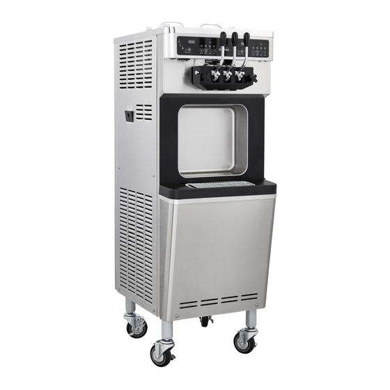
SOFT ICE CREAM FREEZER
SSI-143S
ISI-143S
* This product is for indoors, so do not use it
outdoors.
* Before using the product, be fully familiar
with the contents in the manual.
Please store this manual in a place where
you can reach it easily for future reference.
*
This user manual contains a product
warranty.
* This appliance can be used by children aged
from 8 years and above and persons
with reduced physical, sensory or mental
capabilities or lack of experience and knowledge
if the have been given supervision or instruction
concerning use of the appliance a safe way
and understand the hazards involved.
Children should be supervised to ensure
that they do not play with the appliance.
User's Manual
Advertisement
Table of Contents

Related Manuals for icetro SSI-143S


Summary of Contents for icetro SSI-143S
- Page 1 SOFT ICE CREAM FREEZER User’s Manual SSI-143S ISI-143S * This product is for indoors, so do not use it outdoors. * Before using the product, be fully familiar with the contents in the manual. Please store this manual in a place where you can reach it easily for future reference.
-
Page 2: Table Of Contents
Dear customers Thank you very much for purchasing a soft ice cream freezer made by ICETRO. For correct use of the product and its maintenance, please read this manual carefully. If a problem occurs while using the product, you can refer to this manual for troubleshooting. -
Page 3: Cautions For Your Safety
Cautions for your safety These are safety related items. So, comply with them at all times! They are meant to protect the safety of users and prevent property damages. 전 원 관 련 Please, read the cautionary items carefully for correct use. 전... -
Page 4: Installation Related Items
Cautions for your safety If you want to leave it Do not connect many unused for a long time, electrical products to then and turn off the earth leakage circuit the earth leakage circuit breaker. Use it breaker. individually. It can cause electrical It can cause fires. -
Page 5: During Use
Cautions for your safety If violated, it can cause death If violated, it can cause severe If violated, it can cause or severe injury. physical injury or property slight physical injury or damages. property damages. Warning Danger Caution During use If the product has weird Do not place water sounds or burning smell... -
Page 6: Part Names And Controllers 6~7
Part names and controllers Front MIXING TANK COVER LEVER MIX TANK TEMPERATURE MIX TANK TEMPERATURE MIX LOW MIX LOW BUTTON ▼ STANDBY WASH AUTO STANDBY WASH AUTO MIX TANK TEMPERATURE MIX TANK TEMPERATURE MIX LOW MIX LOW DISPLAY STANDBY AUTO STANDBY WASH AUTO... - Page 7 Part names and controllers BRUSH DASHER COVER PACKING MANUAL PACKING BRUSH 3 PISTON CABURATOR PACKING BEARING CABURATOR DASHER HANDLE JAVARA PATITION FOOD ORIFFICE HINES DASHER LUG...
-
Page 8: Check Prior To Use
Check prior to use Make sure to check them prior to use! This product is exclusively for 1Ø, 240V~, 50Hz / 220V~, 60Hz Install it independently with an earth leakage circuit breaker with more than 30A and provide an external grounding. (Ask a qualified electrical technician for the installation.) The power cable should be connected before the product can operate normally. -
Page 9: Button Display Names And Functions
Button display names and functions ② “MIX TANK ① “MIX LOW” lamp TEMPERATURE” Lamp blinks when there Display the ingredient are insufficient ingredients temperature inside the and It blinks when there is hopper. no ingredient. ⑦ “FREEZING CONTROL LEVEL” button Icecream Level Adjustment button ⑥... -
Page 10: How To Make Soft Cream
How to make soft cream How to make soft cream 1. Fill the mixing tank with mix of such a level that the mix sufficiently covers the sensor (Check whether the “MIX LOW” lamp is turned off.) Level Sensor 2. Plug in the caburator and block the hole. (See page 12 for information about carburator.) 3. -
Page 11: Conversion Function Between Ice-Cream Mode And Yogurt Mode
Conversion function between ice-cream mode and yogurt mode Conversion function between ice-cream mode and yogurt mode 1) The default mode is the ice-cream mode. 2) The modes can be distinguished by checking LED’s; lighting for the ice-cream mode, and blinking for the yogurt mode. ①... -
Page 12: Caburator Control
Caburator control The caburator is made up of two parts. The part that is inserted into the hole of the mixing tank is called the body and a tube is inserted into this. The tube has a hole at the top and at the bottom. -
Page 13: Soft Ice Cream Out-Speed Control
Soft ice cream out-speed control By adjusting screw adjust at the bottom of the lever (out lever), you can adjust the out-speed of the soft ice cream. As shown in the figure on the left, release the ‘screw adjust’ to increase the out-speed of the soft ice cream. -
Page 14: Cleaning Method
Cleaning method Wash mode 1. Press the wash button on the control panel. (Wait until the soft cream in the cylinder is melted. About 10 minutes.) 2. Remove the mixing tank cover. 3. Take out the caburator (tube) 4. Take out the caburator (body). - Page 15 Cleaning method Wash mode 5. Remove the soft cream liquid in the mixing tank and pour faucet water into it. Repeat it two or three times until you get clean water from it. 6. Clean up the inside of the mixing tank with a soft towel and detergent.
- Page 16 Cleaning method Wash mode 8. Brush the drain hole of the mixing tank thoroughly. 9. Use faucet water to clean off the inner area of the tank. 10. Press the wash button and finally discharge the water from the mixing tank. Use faucet water to rinse off the cleaning agent residuals.
-
Page 17: Washing Of Each Parts 17~19
Cleaning method Washing of each parts 11. Press the wash button to stop the product. 12. Release the two dasher cover bolts. 13. Separate the dasher cover from the main body. 14. Separate the dasher from the cylinder. - Page 18 Cleaning method Washing of each parts 15. Brush off the inner area of the cylinder and wipe it off with soft cloth. Insert a brush into the dead end of the cylinder and turn the brush left and right to clean up the cylinder.
- Page 19 Cleaning method Washing of each parts 20. Disassemble the dasher cover assembly, BEARING DASHER BEARING DASHER wash all the parts using neutral detergent and wipe them with soft cloth. DASHER COVER DASHER COVER PACKING PACKING MIXING SHAFT MIXING SHAFT 21. Clean the piston assembly hole of the dasher cover with a brush and soft cloth.
-
Page 20: Dasher Cover Assembly Method
Dasher cover assembly method Dasher cover assembly 1. Apply edible vegetable oil to the ring inserted into the piston. 2. Insert the piston in the dasher cover. 3. Take out the handle shaft of the dasher cover to the right, separate the handle. 4. -
Page 21: Dasher And Dasher Cover Assembly Method
Dasher and dasher cover assembly method Condenser and filter cleaning method 1. Pull out the condenser filter located on the right side of the machine. 2. Remove dust from the filter element or use a vacuum cleaner, and wash it clean with water. -
Page 22: Installation Method
Installation method Electrical connection 1. Supply AC 1PH 220V-240V electricity ※ Maintain space of 50cm or more each between to an additional power distribution the walls and the right and rear sides 20cm box with an earth leakage circuit or more between the left of the system. breaker of a capacity of more than 30 A is individually installed. -
Page 23: Service For Refrigerant Lines 23~25
Service for Refrigerant Lines Removal and replacement of freezing parts CAUTION 1. This unit should be diagnosedd and repaired only by quali to reduce the risk of death, electric shock, serious inj 2. Move the ELCB switch to the "OFF" position before servicing 3. - Page 24 Service for Refrigerant Lines 1. Refrigerant Recovery This ice cream vending machine has a refrigerant service valve (nipple). Recover the refrigerant through this nipple and keep the recovered refrigerant in an approved storage bin. Never discharge the recovered refrigerant to the atmosphere. 2.
- Page 25 Service for Refrigerant Lines 3. Vacuuming and recharging (R-404A) 1) Install the vacuum pump on the system. Connect the charging hoses on the charging nipples of both high-pressure and low-pressure ends. IMPORTANT The vaccum level and vacuum pump may be the same as those for current refrigerants. However, the rubber hose and gauge manifold to be used for evacuation and refrigerant charge should be exclusively for POE oils.
-
Page 26: Removal And Replacement
Removal and Replacement of Compressor B. Removal and Replacement of Compressor WARING 1. Always install a new drier every time the sealed refrigeration system is opened. 2. Do not replace the dried until after all other repair or replacement has been made. Install the new drier with the arrow on the drier in th 3. -
Page 27: Removal And Replacement
Removal and Replacement of Capillary Tube C. Removal and Replacement of Capillary Tube CAUTION 1. Always install a new drier every time the sealed refrigeration system is opened. 2. Do not replace the dried until after all other repair or replacement has been made. Install the new drier with the arrow on the drier in th 3. -
Page 28: Removal And Replacement
Removal and Replacement of Condenser' E. Removal and Replacement of Condenser' WARING 1. Always install a new drier every time the sealed refrigeration system is opened. 2. Do not replace the dried until after all other repair or replacement has been made. Install the new drier with the arrow on the drier in th 3. -
Page 29: Replacement Of Fan Motor
Replacement of Fan motor F. Replacing the fan motor 1) Turn off the power of ELCB. 2) Open the back panel cover. 3) Remove the harness from the fan motor. 4) Remove the four screws from the fan motor assembly. 5) Remove the fan motor and the fastening brackets (total of four bolts). -
Page 30: Before Requesting Service 30~31
Before requesting service The soft ice cream freezer can operate abnormally because you are not familiar with the method for use or due to another insignificant reason. It does not necessarily mean a malfunction. In this case, check the following items to resolve a simple problem on your own without the help from the service center. -
Page 31: Error Code Types
Before requesting service 1. This product is an industrial machine and has some operation noise when compared to household appliances.This product is designed to generate noise The noise is that is less than 70dB. disturbing! the customer satisfaction team in case abnormal noise is generated during machine operation. -
Page 32: Circuit Diagram
Wiring diagram... -
Page 33: Product Specification 전원관련
Product specification Item Spec UNIT Specifications Indefinite (a 100 cc serving every 30 May vary depending seconds) based on ambient temperature Selling capacity on the ice cream of 38 C, humidity of 60%, and mix maker and mixes. temperature of 5 C or lower. -
Page 34: Refrigerant Circuit
Refrigerant circuit Mix tank Capillary Dryer E.P.R Thermostat Suction pipe MANIFOLD For keeping in the refrigerator Comperssor Freezer Automatic Expansion Valve Thermostat Service Port Condenser Vacuum R404A Pump Moter Scales For keeping H.P S/W in the freeze Compressor Discharge pipe Charging Refrigerant ①... -
Page 35: Part List 35~39
Part List OUTSIDE ASS’Y [OUTSIDE ASS'Y] GRIP HANDLE COVER FOOD PAN GASKET FOOD PAN BOLT COVER POM SIDE PANEL L TOP COVER BACK PANEL FRONT COVER TOP SIDE PANEL R FRONT COVER DRAIN BOX FILTER CONDENSER DRAIN BOX UP SIDE PANEL R DOWN ASS'Y FRONT PANEL DOWN FOOT CASTER... - Page 36 [MOVING PART] MOVING PART CABURATOR ADJUST PACKING SENSOR-B BEARING DRUM SENSOR RING NUT(M5) SENSOR POST CABURATOR TUBE BODY SENSOR PACKING SENSOR POLE RING BEARING SHAFT SET BOLT SHAFT CONECTOR 143 BELT PULLY TOP DRUM ASSY 143 GEARED MOTOR 143 V-BELT BOLT HEX BELT PULLY DOWN FRAME GEAR MOTOR L...
- Page 37 Part List DASHER ASS’Y...
- Page 38 [CONTROL BOX ASS'Y] [CONTROL BOX ASS'Y] CONTROL BOX COVER CONTROL BOX ASS’Y CONTROL BOX COVER MAGNET EMPR RELAY CONTROL BOX MAGNET EMPR CONTROL PCB RELAY CONTROL BOX CONTROL PCB MOTOR1 COMP1 HPS1 MOTOR1 COMP1 SWITCH HPS1 TERMINAL BLOCK COMP3 HPS2 SWITCH COMP2 TERMINAL BLOCK...
- Page 39 Part List CONDENSER FAN MOTOR ASS’Y [CONDENSER FAN MOTOR ASS'Y] CAPILLARY 09200 FILTER DRIER E.P.R EXPANSION VALVE COMPRESSOR FILTER DRIER CONDENSER ASS'Y HIGH PRESSURE S/W FAN MOTOR COMPRESSOR CHARGE NIPPLE ASS'Y...
- Page 40 Online Internet Service http://www.icetro.com 3 2 4 0 2 1 5 - 0 3...
Need help?
Do you have a question about the SSI-143S and is the answer not in the manual?
Questions and answers
How to order new Lever¿ what is used to lubricte the freezer?