Table of Contents
Advertisement
Available languages
Available languages
Quick Links
FOLLOWSPOT
ROXIE - 1166 / C - Version V2
VALIDATION: 26/01/22
DN41087001-B (EN)
Robert Juliat S.A.S. 32, rue de Beaumont, F 60530 Fresnoy-en-Thelle - phone : +33 (0)3 44 26 51 89 - fax : +33 (0)3 44 26 90 79 - info@robertjuliat.fr
REF
300W LED FOLLOWSPOT
www.robertjuliat.com
Standard
North American
1166
1166C
Advertisement
Chapters
Table of Contents

Related Manuals for Robert Juliat ROXIE


Summary of Contents for Robert Juliat ROXIE
- Page 1 ROXIE - 1166 / C - Version V2 VALIDATION: 26/01/22 DN41087001-B (EN) Robert Juliat S.A.S. 32, rue de Beaumont, F 60530 Fresnoy-en-Thelle - phone : +33 (0)3 44 26 51 89 - fax : +33 (0)3 44 26 90 79 - info@robertjuliat.fr www.robertjuliat.com...
-
Page 2: Table Of Contents
6.1.10 Exploded view / Spare parts list ..........................17 7 Troubleshooting ................................. 18 7.1 General information ............................. 18 Robert Juliat reserve the right to change or alter any of the items detailed on this page, to increase or improve manufacturing techniques without prior notice. -
Page 3: User's Instructions
1 User’s instructions GENERAL INSTRUCTIONS Not for residential use. These fixtures must only be serviced by a qualified technician. In addition to the instructions indicated on this page, relevant health and safety requirements of the appropriate EU Directives must be adhered to at all times. This fixture is in compliance with section 17 - Lighting appliance for theatre stages, television, cinema and photograph studios. -
Page 4: Presentation
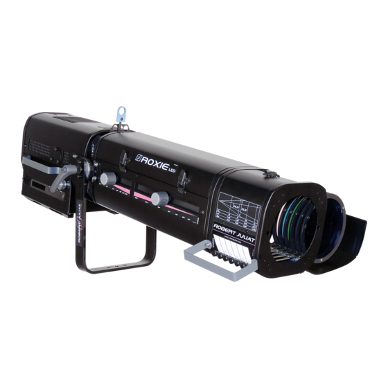
Presentation Functions Functions Identification plate 12. Tilt locking handle Data connectors (IN and OUT) 13. Gate: slots for gobo holder and/or iris Power connectors (IN and OUT) 14. Dimmer rotary knob Thermal breaker 15. Colour changer Power switch 16. Focus adjustment Control board 17. -
Page 5: Identification Label
Identification label Description 1. MOD. : Model 19 15 16 2. VERS. : Version 3. U : Nominal voltage input (V) 4. I : Nominal intensity (A) 5. P : Maximum power input (W) 6. IP : International Protection Rating 7. -
Page 6: Optional Accessories
2.4 Optional accessories Reference Description VD120 120 x 120 mm frosted glass GT800 Tripod stand GT800 - SWL: 40 kg max. height 1550 mm GT1000 Tripod stand GT1000 - SWL: 40 kg max. height 1550 mm Kit TELRAD Followspot sight with riser W-DMX/ZF2 W-DMX Wireless DMX antenna Followspot mount for 50 mm diam. -
Page 7: Set-Up
Set-up 3.1 Mechanics 3.1.1 Operating positions 35° max. 65° max. 3.1.2 Minimum distance between a flammable material and the lighting unit 0,55 m 1.9 ft 3.1.3 Instructions for use Minimum : Maximum : 5°C 40°C 41°F 104°F IP20 - Indoor use only 3.1.4 Lifting •... -
Page 8: Stand Set-Up
3.1.5 Stand set-up • Compatible stands : GT800 & GT1000 Please refer to the relevant user manual for further details. 3.2 Electrical information 3.2.1 LED source Never touch or scratch the LED surface. Cf. EN-19, 6.1.4 LED cleaning procedure if cleaning is necessary. 3.2.2 Power supply Power supply Voltage... - Page 9 Power cable Power cable Connector Mains plug Cable type Cable length Wiring Live: Brown Standard 3G1.5 CEE7/7 Neutral: Blue Neutrik® version H07RNF 9.8 ft Ground: Yellow/Green powerCON TRUE1 North 14AWG Live: Black 1.5 m NAC3FX American SJ TYPE Neutral: White 4.9 ft version (UL/CSA)
-
Page 10: Data
3.2.3 Data DATA Protocol Input connector Output connector USITT DMX 512-A XLR 5-pin XLR 5-pin DATA connectors PIN # Description Shielding Foil & Braided Shield DMX (-) conductor of 1 twisted pair DMX (+) conductor of 1 twisted pair Not used conductor of 2 twisted pair DMX OUT... -
Page 11: Accessories
Accessories 3.3.1 Iris 3.3.2 Gobo holder Gobo DImensions, Cf. EN - 14 3.3.3 Colour changer unit - push-pull Gel filter Clips (Parisien) DImensions, Cf. EN - 14 (3 pieces on each frame) EN - 9 -... -
Page 12: Operations
4 Operations 4.1 Light intensity 4.1.1 Range 100% • Dimming 4.1.2 Control Remotely with DMX512-A protocol Locally via rotary knob DMX512-A HTP mode (Highest Takes Precedence): Light output is the highest value of DMX512 command or local control Focus mode: when standby screen displayed, Push Exit →... - Page 13 Smoothing (SMOOTHING) : Mode Smoothing Slow Slow transition between 2 levels – equivalent to 1000W filament Fast Fast transition between 2 levels – equivalent to 600W filament Without Deactivated – Very fast transitions Master mode (MASTER CONTROL): In order to supervise the operator from the console, a 3rd DMX channel is used: Master control. This channel limits the maximum value of the dimmer shutter.
-
Page 14: Beam Size Adjustment
4.2 Beam size adjustment 4.2.1 Range Beam angle Field angle Model Angles Minimum angle Maximum angle Beam angle 10.6° 15.5° 1166 Field angle 11° 22.1° 4.2.2 Control FOCUS ZOOM FOCUS ZOOM 4.3 Strobe 4.3.1 Range 0 = OFF 55Hz EN - 12 -... -
Page 15: Control
4.3.2 Control Remotely with DMX512-A protocol DMX512-A 4.4 Pan / Tilt 4.4.1 Range Function Range 0 —> 360° TILT Tilt up = 0 —> 35° Tilt down = 0 —> 65° Down 4.4.2 Control Unlock Lock EN - 13 -... -
Page 16: Iris
4.5 Iris 4.5.1 Range • Irising 100% 4.5.2 Control 4.6 Gobo 4.6.1 Range Type Standard gobo - A size 100 mm • Metal 72 mm Dimensions • Glass Maximum • Frosted glass image size Values are in millimeters (mm) Installation Cf. -
Page 17: Dmx Controls
5 DMX Controls 5.1 Control board 5.1.1 Display and Controls exit select ERROR DATA Function Display Exit the current menu option and/or go back Scrolls through menus and/or Decrease blinking data value Scrolls through menus and/or Increase blinking data value Enter the current menu option and/or valid Hard CPU reset DMX and system LED feedback... -
Page 18: Reset
5.1.4 Reset • Reset to default settings: Menu: Fixture Reset → press Select → Yes & press Select to validate 5.1.5 Feedback information • DMX and system LED feedback (see display & controls 7 , Cf. EN-15): ⇒ Green= DMX512 frame detected ⇒... -
Page 19: Optics
The dimming level is then recalculated depending on the limitation. 6.1.10 Exploded view / Spare parts list www.robertjuliat.com Available on ⇒ ⇒ Or on request through the Robert Juliat Service department info@robertjuliat.fr ⇒ ⇒ EN - 17 -... -
Page 20: Troubleshooting
Troubleshooting 7.1 General information SYMPTOMS POSSIBLE REASONS SOLUTIONS Display Check the AUTO-OFF display in the switches on Display auto off mode activated when button Fixture Setup is pressed Display OFF Check : Display still off • power when button No power •... - Page 21 ROXIE - 1166 / C - Version V2 VALIDATION: 26/01/22 DN41087001-B (FR) Robert Juliat S.A.S. 32, rue de Beaumont, F 60530 Fresnoy-en-Thelle - tél. : +33 (0)3 44 26 51 89 - fax : +33 (0)3 44 26 90 79 - info@robertjuliat.fr www.robertjuliat.fr...
- Page 22 6.1.10 Nomenclature / Pièces détachées ..........................17 7 Dépannage ..................................18 7.1 Informations générales ............................. 18 Robert Juliat se réserve le droit de modifier sans préavis le contenu de ce document ou les caractéristiques de ses produits dans un souci permanent d'amélioration.
-
Page 23: Instructions D'utilisation
1 Instructions d’utilisation CONSIGNES GÉNÉRALES Impropre à l'usage domestique. Matériel professionnel : intervention par technicien qualifié uniquement. Outre les consignes d’utilisation figurant dans la présente notice, vous devrez respecter les prescriptions générales de sécurité et de prévention des accidents édictée par le législateur. L’appareil auquel est attachée cette notice rentre dans la section 17 - Luminaires pour éclairage de scènes de théâtre, des studios de télévision, de cinéma et de photographie de la norme : Standards NF EN 60598-1, NF EN 60598-2-17, Low Voltage Directive 2014/35/UE &... -
Page 24: Présentation
Présentation Fonctions Fonctions Plaque d'identification 12. Poignée verrouillage de la fourche Connecteurs DATA (entrée et sortie) 13. Fenêtre : glissières pour support gobo et/ou iris Connecteurs d'alimentation (entrée et sortie) 14. Boutton d'obturateur (dimmer) Thermal breaker 15. Changeur de couleurs Interrupteur mise sous tension 16. -
Page 25: Plaque D'identification
Plaque d’identification Description 1. MOD. : modèle de l’appareil 2. VERS. : Version de l’appareil 19 15 16 3. U : Tension nominale (V) 4. I : Intensité nominale (A) 5. P : Puissance maximum (W) 6. IP : Indice de protection international 7. -
Page 26: Accessoires Optionnels
Accessoires optionnels Référence Description VD120 120 x 120 mm verre déploi GT800 Trépied GT800 - CMU: 40 kg hauteur max. : 1550 mm GT1000 Trépied GT1000 - CMU: 40 kg hauteur max. : 1550 mm Kit TELRAD Viseur de poursuite TELRAD avec extension W-DMX/ZF2 Antenne W-DMX san-fils DMX Support poursuite pour structure Ø... -
Page 27: Installation
Installation Mécanique 3.1.1 Positions d’utilisation 35° max. 65° max. 3.1.2 Distance minimale entre l’appareil et une matière inflammable 0,55m 1.9 ft 3.1.3 Conditions d’utilisation Minimum : Maximum : 5°C 40°C 41°F 104°F Indice de Protection international: IP20 – Utilisation intérieure uniquement 3.1.4 Levage •... -
Page 28: Mise Sur Pied
3.1.5 Mise sur pied • Pieds compatibles : GT800 & GT1000. Veuillez vous reporter au manuel pieds pour plus d'information. 3.2 Electrique 3.2.1 Source LED Ne jamais toucher la surface de la source LED. Cf. FR-19, 6.1.4 Procédure de nettoyage de la source LED si nécessaire. 3.2.2 Alimentation Puissance Tension... - Page 29 Cordon d’alimentation Connecteur Fiche Cordon Câble Longueur Câblage projecteur d’alimentation Phase: marron Version CEE7/7 FJUC000112 Neutre: bleu Neutrik® standard 9.8 ft Terre: jaune/vert powerCON TRUE1 Phase: noir Version nord- 1.5 m NAC3FX FJUC000113 Neutre: blanc américaine 4.9 ft Terre : vert Mise sous tension FR - 7 -...
- Page 30 3.2.3 Data DATA Protocole Connecteur d’entrée Connecteur de sortie USITT DMX 512-A XLR 5-pin XLR 5-pin DATA connecteurs PIN # Description Masse Tresse métallique DMX (-) 1er conducteur de la paire torsadée 1 DMX (+) 2e conducteur de la paire torsadée 1 Non utilisé...
-
Page 31: Accessoires
3.3 Accessoires 3.3.1 Iris 3.3.2 Support gobo Gobo DImensions, Cf. FR - 14 3.3.3 Changeur de couleurs à tirettes Filtre gélatine Clips (Parisien) DImensions, Cf. FR - 14 (3 pièces pour chaque support filtre) FR - 9 -... -
Page 32: Opération
4 Opération 4.1 Intensité lumineuse 4.1.1 Etendue • Gradation 100% 4.1.2 Contrôle A distance via le protocole DMX512-A Localement via bouton DMX512-A Gestion des commandes en mode HTP : Les deux valeurs d’entrée sont comparées, la valeur la plus élevée est retenue Focus mode: en mode écran d’accueil, Appui sur →... - Page 33 Lissage (SMOOTHING) : Mode Lissage Slow Transitions lentes entre valeurs – simule l’inertie de lampe halogène 1000W Fast Transitions rapides entre valeurs – simule l’inertie de lampe halogène 600W Without Pas de lissage – Transitions très rapides entre valeurs Master mode (MASTER CONTROL): Afin de prendre la main sur le contrôle local (l’opérateur) à...
-
Page 34: Ajustement De La Taille Du Faisceau
4.2 Adjustement de la taille du faisceau 4.2.1 Etendue Beam angle Field angle Model Angles Minimum angle Maximum angle Beam angle 10.6° 15.5° 1166 Field angle 11° 22.1° 4.2.2 Contrôle FOCUS ZOOM FOCUS ZOOM 4.3 Stroboscope 4.3.1 Etendue 0 = éteinte 55Hz FR - 12 -... -
Page 35: Contrôle
4.3.2 Contrôle A distance via le protocole DMX512-A DMX512-A 4.4 Orientation 4.4.1 Etendue Fonction Etendue 0 —> 360° TILT TU = 0 —> 35° TD = 0 —> 65° 4.4.2 Contrôle Verrouiller Déverrouiller FR - 13 -... -
Page 36: Iris
4.5 Iris 4.5.1 Etendue 100% 4.5.2 Contrôle 4.6 Gobo 4.6.1 Etendue Type Gobo standard - Taille A 100 mm • Métal 72 mm Dimensions • Verre Taille d'image • Dépoli maximum Unités en millimètres (mm) Installation Cf. section: 3.3.2, page FR - 9 4.7 Couleur •... -
Page 37: Commande Dmx
5 Commande DMX Panneau de contrôle 5.1.1 Afficheur et touches exit select ERROR DATA Function Afficheur LCD Sortie du menu et/ou retour en arrière Défilement des menus et/ou diminution des valeurs sélectionnées Défilement des menus et/ou augmentation des valeurs sélectionnées Sélection du menu et/ou validation Reset système Voyants d’état système et data... -
Page 38: Reset
5.1.4 Reset • Retour vers les paramètres par défaut : Menu: FIXTURE RESET (réinitialisation) → button Select → YES → button Select pour validation. 5.1.5 Retour d'information • Voyant d’état système et data , (Cf. FR-15) : ⇒ Vert = Signal DMX512 détecté. ⇒... -
Page 39: Optique
6.1.5 Optique Le nettoyage des éléments optiques (lentilles) s’effectue avec des nettoyants à base d’alcool spécifique pour optique. Accès aux lentilles du zoom 6.1.6 Analyse Si le problème persiste après avoir suivi la procédure de dépannage (Cf. section 7), veuillez contacter un revendeur RJ agréé avec les informations suivantes : •... -
Page 40: Dépannage
Dépannage Informations générales SYMPTOMES CAUSES POSSIBLES SOLUTIONS L’afficheur s’allume La fonction d’extinction Vérifier la fonction AUTO-OFF dans le réglage lorsqu’une automatique de l’afficheur est de l'appareil touche est activée pressée Afficheur éteint Vérifier : L’afficheur • l’alimentation Le projecteur n’est pas ne s’allume •...
Need help?
Do you have a question about the ROXIE and is the answer not in the manual?
Questions and answers