Table of Contents
Advertisement
Quick Links
Operation, Parts
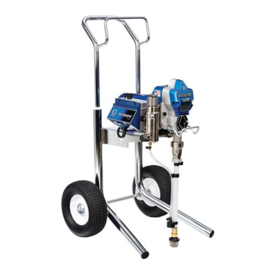
RentalPro 230PC
Electric Airless Sprayer
For professional use only.
Not approved for use in explosive atmospheres or hazardous locations.
For portable airless spraying of architectural paints and coatings.
Model: 17C407
3300 psi (228 bar, 22.8 MPa) Maximum Working Pressure
Important Safety Instructions
Read all warnings and instructions in this manual and related manuals.
Be familiar with the controls and the proper usage of the equipment.
Save these instructions.
Gun - 3A6285 (Contractor PC)
Use only genuine Graco replacement parts.
The use of non-Graco replacement parts may void warranty.
Related Manuals
Pump - 334599
ti25193a
334603E
EN
Advertisement
Table of Contents

Subscribe to Our Youtube Channel
Related Manuals for Graco 17C407


Summary of Contents for Graco 17C407
- Page 1 Be familiar with the controls and the proper usage of the equipment. Save these instructions. Related Manuals Gun - 3A6285 (Contractor PC) Pump - 334599 ti25193a Use only genuine Graco replacement parts. The use of non-Graco replacement parts may void warranty.
-
Page 2: Table Of Contents
Graco Standard Warranty ........ -
Page 3: Warnings
Warnings Warnings The following warnings are for the setup, use, grounding, maintenance, and repair of this equipment. The exclamation point symbol alerts you to a general warning and the hazard symbols refer to procedure-specific risks. When these symbols appear in the body of this manual or on warning labels, refer back to these Warnings. - Page 4 All parts of the spray system, including the pump, hose assembly, spray gun, and objects in and around the spray area shall be properly grounded to protect against static discharge and sparks. Use Graco conductive or grounded high-pressure airless paint sprayer hoses.
- Page 5 Check hoses and parts for signs of damage. Replace any damaged hoses or parts. • This system is capable of producing 3300 psi. Use Graco replacement parts or accessories that are rated a minimum of 3300 psi. • Always engage the trigger lock when not spraying. Verify the trigger lock is functioning properly.
- Page 6 Warnings ELECTRIC SHOCK HAZARD This equipment must be grounded. Improper grounding, setup, or usage of the system can cause electric shock. • Turn off and disconnect power cord before servicing equipment. • Connect only to grounded electrical outlets. • Use only 3-wire extension cords. •...
-
Page 7: Component Identification
Component Identification Component Identification M Drain Tube ON/OFF Switch Fluid Intake Pressure Control Pump Display Fluid Outlet Prime Valve Hanger Tip Guard Filter Spray Tip Finger Guard / TSL Fill Point Pail Hook Airless Hose Model/Serial Tag (Not shown, located Power Cord on bottom of unit.) Trigger Lock... -
Page 8: Grounding
Grounding Grounding The equipment must be grounded to reduce the risk of static sparking and electric shock. An electric or static spark can cause fumes to ignite or explode. An improper ground can cause electric shock. A good ground provides an escape wire for the electric current. -
Page 9: Pressure Relief Procedure
Pressure Relief Procedure Pressure Relief Procedure Turn pressure control to lowest setting. Follow the Pressure Relief Disengage the trigger lock. Procedure whenever you see this symbol. This equipment stays pressurized until pressure is manually relieved. To help prevent serious injury from pressurized ti24603b fluid, such as skin injection, splashed fluid and moving parts, follow the Pressure... - Page 10 Pressure Relief Procedure Turn prime valve down. Put drain tube VERY SLOWLY loosen the tip in a pail. Leave prime valve in down guard retaining nut or the hose end (drain) position until you are ready to coupling to relieve pressure spray again.
-
Page 11: Setup
When first setup is performed Use wrenches to tighten securely. remove shipping plug from fluid outlet. Engage trigger lock. Connect Graco airless hose to fluid outlet. Use wrenches to tighten securely. Remove tip guard. ti24616a... - Page 12 Setup When unpacking sprayer for the first Make certain ON/OFF switch is OFF. time remove packaging materials from inlet strainer. After long term storage check inlet strainer for clogs and debris. ti24586a Plug power supply cord into a properly grounded electrical outlet. ti24651a 10.
- Page 13 Setup 11. Turn prime valve down. 13. Turn pressure control to lowest setting. 14. Turn ON/OFF switch to ON position. 15. Increase pressure 1/2 turn to start motor. Allow fluid to flush through sprayer for fifteen seconds. 16. Turn prime valve horizontal. Disengage trigger lock.
-
Page 14: Startup/Prime
Startup/Prime Startup/Prime Turn ON/OFF switch to ON position. Perform Pressure Relief Procedure, page 9. ti24644a Turn pressure control to lowest pressure. Increase pressure 1/2 turn to start motor. Allow paint to circulate through sprayer until paint flows out the drain tube. - Page 15 Startup/Prime Hold gun against grounded metal waste pail. Trigger gun until paint appears. High-pressure spray is able to inject toxins into the body and cause serious bodily injury. Do not stop leaks with hand or rag. Inspect for leaks. If leaks occur, perform Pressure Relief Procedure, page 9, then tighten all fittings and repeat Startup procedure.
-
Page 16: Operation
Operation Operation Spray Tip Installation Screw assembly onto gun. Tighten. Perform Pressure Relief Procedure, page 9. ™ Use spray tip (A) to insert OneSeal (B) into tip guard (C). Spray When a RAC X™ FF LP Fine Finish Low ti24653a Pressure reversible spray tip is used, Insert Spray Tip. -
Page 17: Clear Tip Clog
Operation Adjust pressure to eliminate heavy Release trigger. Engage trigger lock. edges. Rotate Spray Tip. Disengage trigger lock. Trigger gun at waste area to clear clog. ti25868a ti25869a Engage trigger lock. Return Spray Tip to original position. Disengage trigger Use smaller tip size if pressure lock and continue spraying. -
Page 18: Digital Display
Operation Digital Display Press and hold display button to change pressure units (psi, bar, or MPa). Some models are equipped with a digital display. This section explains how to use this feature. Pressure Display Perform Pressure Relief Procedure, page 9. Plug sprayer into grounded outlet. - Page 19 Operation Sprayer model number is displayed To erase last error code, press and followed by Data Point 1 which is the hold display button. unit power on time in hours. Press display button again to display Data Point 4. The software revision is displayed.
-
Page 20: Cleanup
Operation Cleanup Remove fluid intake and drain tube from paint, wipe excess paint off outside. Perform Pressure Relief Procedure, page 9. Remove tip guard and Spray Tip. For additional information, see separate gun manual. ti24709a 334603E... - Page 21 Operation Place fluid intake in flushing fluid. Use While continuing to trigger gun, turn water for water base paint and mineral prime valve down. Then, release gun spirits for oil-based paint. Place drain trigger. Allow flushing fluid to circulate tube in waste pail. until fluid comes out of drain tube clear.
- Page 22 Operation 10. Turn prime valve horizontal. Trigger 14. Remove filter from gun and sprayer if gun into flushing pail to purge fluid from installed. Clean and inspect. Install hose. filter. See separate gun manual. 11. Engage trigger lock. 12. Perform Pressure Relief Procedure, page 9, to verify that there is no residual pressure in the system.
- Page 23 Operation 15. If flushing with water, flush again with 16. Wipe sprayer, hose and gun with a rag mineral spirits or Pump Armor to leave soaked in water or mineral spirits. a protective coating to prevent freezing or corrosion. ti25214a ti25213a 334603E...
-
Page 24: Maintenance
Maintenance Maintenance Routine maintenance is important to ensure proper operation of your sprayer. Maintenance includes performing routine actions which keep your sprayer in operation and prevents trouble in the future. Activity Interval Inspect/clean sprayer filter, fluid inlet strainer, and gun Daily or each time you spray filter. -
Page 25: Troubleshooting
Troubleshooting Troubleshooting Mechanical/Fluid Flow Follow Pressure Relief Procedure, Check all possible problems and page 9, before checking or repairing. causes before disassembling the unit. What to Check What to Do If check is OK, go to next When check is not OK, Problem check refer to this column... - Page 26 Troubleshooting What to Check What to Do If check is OK, go to next When check is not OK, Problem check refer to this column Pump output is low Pump rod damage. Repair pump. See pump manual. Low stall pressure. Turn pressure knob fully clockwise.
- Page 27 Troubleshooting What to Check What to Do If check is OK, go to next When check is not OK, Problem check refer to this column Fluid is spitting from gun Air in pump or hose. Check and tighten all fluid connections.
-
Page 28: Electrical
Troubleshooting Electrical View digital display or remove control box cover to view control board status light. To determine which code (or any Symptom: Sprayer does not run, stops other code besides voltage supply) running, or will not shut off. refer to the control board status light. Turn the ON/OFF switch OFF, remove the control cover then turn power back ON. - Page 29 Troubleshooting Problem What to Check How to check Check transducer or transducer Sprayer does not run at all Make sure there is no pressure in the system (see Pressure Relief connections Procedure, page 9). Check fluid path Display shows E=02 for clogs, such as clogged filter.
- Page 30 Troubleshooting Problem What to Check How to check Sprayer does not run at all Check voltage supply to the sprayer Turn ON/OFF switch OFF and (control board is detecting a multiple disconnect power to sprayer. voltage surges). Locate a good voltage supply to Display shows E=04 prevent damage to electronics.
- Page 31 Troubleshooting Problem What to Check How to check 6.Connect the Red and Black leads from the motor to an Ohm meter. Rotate the motor while checking for opens. If an open is found replace the motor. BLACK (-) RED (+) YELLOW 1-3 ohms ti24723a...
- Page 32 Troubleshooting Problem What to Check How to check 8.Use an Ohm meter to check motor for shorts. Connect (–) meter lead to motor case. Move the (+) meter lead to each motor wire. Meter should read open on all wires. GROUND BLACK YELLOW...
- Page 33 Troubleshooting Problem What to Check How to check Basic electrical problems Motor leads are securely fastened Replace loose terminals; crimp to and properly mated leads. Be sure terminal are firmly connected. Clean circuit board terminals. Securely reconnect leads. For loose motor brush lead Tighten terminal screws.
- Page 34 Troubleshooting Sprayer Will Not Run (See following page for steps) Sprayer Will Not Run (see following pages for steps) Remove Control box cover. Turn sprayer ON. Observe control board status light on See Step 1. Do you control board (see page 27). have over 100 VAC? No Light Once...
- Page 35 Troubleshooting Step 1: Step 3: Plug Power cord in and turn Check motor thermal switch. switch ON. Connect probes Unplug yellow wires. Meter to L and N on control board. should read continuity. Turn meter to AC Volts. NOTE: Motor should be cool during reading.
- Page 36 Troubleshooting Sprayer Will Not Shut Off Remove control box cover so the control board status light can be viewed if available. Perform Pressure Relief Procedure, page 9. Leave prime valve open (down) and turn ON/OFF switch OFF. Troubleshooting Procedure Plumb pressure gauge into paint hose, Mechanical problem: plug sprayer in, and turn power switch ON.
-
Page 37: Sprayer Parts
Sprayer Parts Sprayer Parts Ref. Torque 140-160 in-lb (15.8 - 18.1 N•m) 30-35 in-lb (3.4 - 4.0 N•m) 23-27 in-lb (2.6 - 3.10 N•m) See page 40. ti25847b 334603E... - Page 38 Sprayer Parts Ref. Torque 140-160 in-lb (15.8 - 18.1 N•m) 30-35 in-lb (3.4 - 4.0 N•m) Hammer tight 25-30 ft-lb (33.8 - 40.7 N•m) ti25153a 334603E...
-
Page 39: Sprayer Parts List
Sprayer Parts Sprayer Parts List Ref. Part Description Qty. Ref. Part Description Qty. 195108 HOSE, drain 117501 SCREW, mach, hex 195697 STRAINER, 7/8-14 unf washer hd 117559 O-ring 17C485 FRAME, cart, hi 17C539 COVER, front, painted 17D296 TUBE, suction, intake 15B465 SHIELD, motor, 17Z644... -
Page 40: Control And Filter
Control and Filter Control and Filter Ref. Torque 140-160 in-lb (15.8 - 18.1 N•m) 30-35 in-lb (3.4 - 4.0 N•m) 20-25 in-lb (2.3 - 2.8 N•m) 37-43 ft-lb (50.2 - 58.3 N•m) 130-150 in-lb (14.7 - 16.9 N•m) ti25154a 334603E... -
Page 41: Control And Filter Parts List
Control and Filter Control and Filter Parts List Ref. Part Description Qty. Ref. Part Description Qty. 195428 BOOT, toggle 117828 PACKING, o-ring 235014 VALVE, drain, 111457 PACKING, o-ring includes 5, 26 111600 PIN, grooved 224807 BASE, valve 277364 GASKET, seat, valve 17D888 POTENTIOMETER, 115494... -
Page 42: Wiring Diagram
Wiring Diagram Wiring Diagram Black ON/OFF Black Switch Power Plug Black White Green Red (+) Black (-) from Motor ti2471a 2 x White 334603E... -
Page 43: Technical Specifications
Technical Specifications Technical Specifications 17C407 Metric Sprayer Maximum fluid working pressure 3300 psi 228 bar, 22.8 MPa Maximum Delivery 0.57 gpm 2.2 lpm Maximum Tip Size 0.023 0.023 Fluid Outlet npsm 1/4 in. 1/4 in. Cycles 700 per gallon 185 per liter... -
Page 44: Graco Standard Warranty
With the exception of any special, extended, or limited warranty published by Graco, Graco will, for a period of twelve months from the date of sale, repair or replace any part of the equipment determined by Graco to be defective.
Need help?
Do you have a question about the 17C407 and is the answer not in the manual?
Questions and answers