Graco True Airless LTS15 Owner's Manual
Hide thumbs
Also See for True Airless LTS15:
- Operation manual (35 pages) ,
- Owner's manual (40 pages) ,
- Operation (35 pages)
Table of Contents
Advertisement
FIRE AND EXPLOSION HAZARD
LTS 15/LTS 17 Models:
•
Use only non-flammable or water-based materials, or non-flammable paint thinners. Do not use
materials having flash points lower than 100° F (38° C). This includes, but is not limited to, acetone,
xylene, toluene, or naphtha. For more information about your material, request Safety Data Sheet
(SDS) from the supplier.
•
Spraying flammable or combustible materials in a factory or fixed location must comply with NFPA
33 and OSHA 1910.94(c) requirements in the USA and with all similar local regulations in other
countries.
Not approved for use in explosive atmospheres or hazardous locations.
For portable airless spraying of architectural paints and coatings.
Important Safety Instructions
Read all warnings and instructions in this manual, related manuals, and on the unit.
Be familiar with the controls and the proper usage of the equipment. Save these
instructions.
3A3529C
EN
Advertisement
Table of Contents

Related Manuals for Graco True Airless LTS15


Summary of Contents for Graco True Airless LTS15
- Page 1 3A3529C FIRE AND EXPLOSION HAZARD LTS 15/LTS 17 Models: • Use only non-flammable or water-based materials, or non-flammable paint thinners. Do not use materials having flash points lower than 100° F (38° C). This includes, but is not limited to, acetone, xylene, toluene, or naphtha.
-
Page 2: Before You Spray
Review Warnings for Important Safety Information Important! Read carefully and practice good safety habits. Review Manual & Watch Videos Scan QR code for Operational Video or go to magnum.graco.com/magop/ Related Manuals Gun: 312830 (SG) ProXChange™ Pump: 3A3172 (ProLTS only) Models 3000 psi (207 bar, 20.7 MPa) Maximum Working Pressure... -
Page 3: Table Of Contents
Graco Standard Warranty ........ -
Page 4: Warnings
Warnings Warnings The following warnings are for the setup, use, grounding, maintenance, and repair of this equipment. The exclamation point symbol alerts you to a general warning and the hazard symbols refer to procedure-specific risks. When these symbols appear in the body of this manual or on warning labels, refer back to these Warnings. - Page 5 Use Graco conductive or grounded high-pressure airless paint sprayer hoses. •...
- Page 6 • Check hoses and parts for signs of damage. Replace any damaged hoses or parts. • This system is capable of producing 3000 psi. Use Graco replacement parts or accessories that are rated a minimum of 3000 psi. • Always engage the trigger lock when not spraying. Verify the trigger lock is functioning properly.
- Page 7 Warnings PRESSURIZED ALUMINUM PARTS HAZARD Use of fluids that are incompatible with aluminum in pressurized equipment can cause serious chemical reaction and equipment rupture. Failure to follow this warning can result in death, serious injury, or property damage. • Do not use 1,1,1-trichloroethane, methylene chloride, other halogenated hydrocarbon solvents or fluids containing such solvents.
-
Page 8: Know Your Sprayer
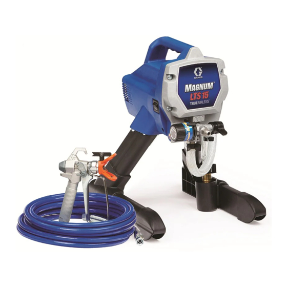
Know Your Sprayer Know Your Sprayer LTS 15 Stand Model ti30912a Pump PushPrime™ Button Inlet Valve Prime/Spray Valve Outlet Valve (airless hose connection) Pressure Control Knob Airless Hose ON/OFF Switch Inlet Strainer Suction Tube Power Cord Drain Tube (with diffuser) W Suction Tube Drip Cup Airless Spray Gun Model/Serial Tag (Not shown, located... - Page 9 Know Your Sprayer LTS 17 Cart Model ti30913a M Gun Filter (inside handle) PushPrime™ Button Pump Prime/Spray Valve Inlet Valve Pressure Control Knob Outlet Valve (airless hose connection) ON/OFF Switch Airless Hose Suction Tube Pail Hanger Drain Tube (with diffuser) Inlet Strainer Airless Spray Gun Power Cord...
- Page 10 Know Your Sprayer ProLTS 170 Stand Model Airless Hose Connection PushPrime™ Button Airless Hose Prime/Spray Valve InstaClean™ Filter (inside fluid outlet) Pressure Control Knob Inlet Strainer ON/OFF Switch Power Cord Suction Tube Easy Access Door Drain Tube (with diffuser) W Suction Tube Drip Cup Airless Spray Gun Pump Removal Tool Reversible Spray Tip...
- Page 11 Know Your Sprayer ProLTS 190 Cart Model ti27117a Airless Hose Connection PushPrime Button Airless Hose Prime/Spray Valve InstaClean Filter (inside fluid outlet) Pressure Control Knob Pail Hanger ON/OFF Switch Inlet Strainer Suction Tube Power Cord Drain Tube (with diffuser) Easy Access Door Airless Spray Gun Pump Removal Tool Reversible Spray Tip...
-
Page 12: Setup
Setup When unpacking sprayer for the first time or after long term storage perform setup procedure. Assemble Your Sprayer Connect Graco airless hose to outlet valve fitting. Use wrench to tighten securely. ti25197a Turn pressure control knob all the way left (counter-clockwise) to lowest set- ting. -
Page 13: Start Up
Start Up Start Up ti25198b Turn pressure control knob to lowest setting. Pressure Relief Procedure Follow the Pressure Relief Procedure whenever you see this symbol. This equipment stays pressurized until ti27493a pressure is manually relieved. To help Put drain tube into a waste pail and turn prevent serious injury from pressurized Prime/Spray valve in PRIME position fluid, such as skin injection or splashed... - Page 14 Start Up If you suspect the spray tip or hose is Turn Prime/Spray valve down to clogged or that pressure has not been PRIME position. fully relieved: VERY SLOWLY loosen the tip guard retaining nut or the hose end coupling to relieve pressure gradually.
- Page 15 Start Up If flushing fluid fails to come out of the drain ProLTS: tube, perform the steps below until flushing fluid flows up the suction tube and out the drain tube. Some fluids prime faster if the ON/OFF switch is toggled on and off so the pump can slow and stop.
- Page 16 Start Up Remove outlet valve and clean. Make Remove suction tube. Remove inlet certain outlet ball moves free in the valve and clean. Make certain the housing. spring is facing up when the inlet ball and valve are installed. Install outlet valve and repeat Flush Storage Fluid, page 14.
- Page 17 Start Up Perform a power flush. See Cleanup with Power Flush Adapter, page 23. LTS15/LTS17 High-pressure spray is able to inject toxins into the body and cause serious bodily injury. Do not stop leaks with hand or rag. Inspect for leaks. If leaks occur, perform Pressure Relief Procedure, page 13, then tighten all fittings and repeat Start Up.
- Page 18 Start Up Fill Gun and Hose Trigger gun into waste pail until only paint comes out of the gun. Hold gun against waste pail. Point gun Release trigger. Engage trigger lock. into waste pail. Transfer drain tube to paint pail and clip Disengage trigger lock.
-
Page 19: How To Spray
How to Spray How to Spray Spray tip must be pushed all the way into the tip guard. Turn spray tip to push down. Spray Tip Installation To prevent spray tip leaks make certain spray ti27145a tip and tip guard are installed properly. Perform Pressure Relief Procedure, Turn the arrow shaped handle on the spray tip forward to the spray... -
Page 20: Adjust Pressure Control
How to Spray Adjust Pressure Control The pressure control knob allows for infinite pressure adjustment. To reduce overspray, always start at the lowest pressure setting and increase pressure to the minimum setting that results in an acceptable spray pattern. 3000 psi 1500 psi 500 psi ti5597b... -
Page 21: Clear Tip Clog
How to Spray Triggering Gun • A smaller spray tip may be needed. • Material may need to be thinned. If Pull trigger after starting stroke. Release material needs to be thinned follow trigger before end of stroke. Gun must be manufacturer’s recommendations. -
Page 22: Cleanup
Cleanup Cleanup Cleaning the sprayer after each use results in Place empty waste and flushing fluid a trouble free start up the next time the pails side by side. sprayer is used. Place suction tube in flushing fluid. Use water for water based paint and mineral spirits or compatible oil-based flushing solvent for oil-based paint. - Page 23 Cleanup 11. Turn ON/OFF switch to OFF position. 16. Turn Prime/Spray valve down to PRIME position. NOTE: Step 12 is for returning paint in hose to paint pail. One 50 ft (15 m) hose holds 17. Turn ON/OFF switch to OFF position. approximately 1 quart (1 liter) of paint.
- Page 24 Cleanup 11. Turn ON/OFF switch to ON position. 12. Open Power Flush attachment valve. 13. Circulate water through sprayer, into waste pail, for 20 seconds. 14. Turn ON/OFF switch to OFF position. NOTE: Step 15 is for returning paint in hose to paint pail.
- Page 25 Cleanup 18. Stop triggering gun. Engage the trigger Check InstaClean Filter (C) for debris. If lock. needed, clean filter with water or flushing fluid and a soft brush. Install closed (square) end of InstaClean Filter (C) in sprayer. Screw outlet valve (B) into sprayer. Tighten outlet valve and reconnect hose ti25196b (A) to sprayer.
-
Page 26: Storage
Storage Storage With proper storage, the sprayer will be ready Engage trigger lock. to use the next time it is needed. ti25196b Leave gun attached to hose. Remove tip and guard and clean with Short Term Storage water or flushing fluid and a brush. Wipe paint off outside of gun using a (up to 2 days) soft cloth moistened with water or flush-... - Page 27 Storage Turn Prime/Spray valve down to Leave gun attached to hose. PRIME position. Remove tip and guard and clean with water or flushing fluid and a brush. 10. Wipe paint off outside of gun using a soft cloth moistened with water or flush- ing fluid.
-
Page 28: Reference
Reference Reference Understanding Tip Number The last three digits of tip number (i.e.: Spray Tip Selection 221413) contain information about hole size and fan width on surface when gun is held 12 in. (30.5 cm) from surface being sprayed. Selecting Tip Size First digit when doubled Spray tips come in a variety of hole sizes for 413 tip has... -
Page 29: Cleaning Fluid Compatibility
Reference Lacquer Conversion Kit Static Grounding Instructions (Oil-Based To spray lacquers with the ProLTS 170 or materials) ProLTS 190, you must purchase a lacquer conversion kit, and follow Static Grounding Instructions (Oil-Based materials), page 29, when using oil-based materials. See ProLTS 170 and ProLTS 190 parts list, page 41 or 47. - Page 30 Reference Always ground a metal pail: connect a To maintain ground continuity when ground wire to the pail. Clamp one end to the sprayer is flushed or pressure is relieved: pail and the other end to a true earth ground hold metal part of spray gun firmly to the side such as a water pipe.
- Page 31 Reference Quick Reference Page 10 Name Description • Prime/Spray Valve In PRIME position directs fluid to drain tube. • In SPRAY position directs pressurized fluid to paint hose. • Automatically relieves system pressure in overpres- sure situations. PushPrime Button Taps the inlet ball when pushed to loosen it. Pressure Control Knob Increases (clockwise) and decreases (counter-clock- wise) fluid pressure in pump, hose, and spray gun.
-
Page 32: Maintenance
Always replace inlet and outlet valves every second time the pump kit is replaced. • See ProXChange Pump Parts (Pro- LTS only), page 48 or consult a Graco/M authorized retailer, dis- AGNUM tributor, or service center. ti27463a 3A3529C... - Page 33 Maintenance ProLTSChange Removal Tool Slide pump assembly off the mounting pins. An integrated tool is included in the frame to remove ProLTSChange packing assembly. See Pump repair manual for complete repair instructions. ti26930a ti26931a 3A3529C...
- Page 34 Maintenance Pump Installation Push on pump rod to slide pump assembly back on to mounting pins. Slide pump assembly onto the mounting Swing easy access door closed while pins. pushing the entire door down. ti27036a Move pump rod up or down until cap is level with the opening in the yoke.
-
Page 35: Troubleshooting
If not frozen, check for hardened paint in pump. If paint has hardened in pump. See page 32. If motor does not turn with pump removed, consult a Graco/ Magnum authorized retailer, distributor, or service center. Motor or control is damaged. - Page 36 Outlet valve ball is stuck or dirty. Unscrew outlet valve, remove, and clean assembly. See page 17. Debris in paint. Strain the paint. See page 12. Prime/Spray valve is worn or Take sprayer to Graco/MAGNUM obstructed with debris. authorized service center. 3A3529C...
- Page 37 Troubleshooting Problem Cause Solution Pump is primed, but can not achieve Spray tip may be partially clogged. Clear spray tip clog. See page 21. good spray pattern. Reversible spray tip is in UNCLOG Rotate arrow-shaped handle on spray position. tip so it points forward to SPRAY position.
- Page 38 Choose spray tip with narrower fan. Make sure gun is close enough to surface. Fan pattern varies dramatically while Pressure control switch is worn and Take sprayer to Graco/M AGNUM spraying. causing excessive pressure variation. authorized service center. Cannot trigger spray gun.
- Page 39 Notes Notes 3A3529C...
-
Page 40: Lts 15: 17K955 Stand Sprayer Parts
LTS 15: 17K955 Stand Sprayer Parts LTS 15: 17K955 Stand Sprayer Parts ti28224a Ref. Torque 20-25 in-lb (2.3-2.8 N•m) 26-32 in-lb (2.9-3.6 N•m) 25-35 in-lb (2.8-4.0 N•m) 80-90 in-lb (9.0-10.0 N•m) 12-16 in-lb (1.4-1.8 N•m) 36-42 in-lb (4.0-4.7 N•m) 3A3529C... - Page 41 LTS 15: 17K955 Stand Sprayer Parts 17K955 Stand Sprayer Parts List Ref. Part Description Qty. Ref. Part Description Qty. 103338 O-RING 17L079 KIT, pump includes 4, 123849 SPRING, inlet 8, 17, 29, 33, 48 257002 KIT, strainer 16E835 DRIVE 15Y296 COVER, wire 112689 SCREW, button, thd 115099 WASHER, hose form...
-
Page 42: Lts 17: 17K960 Cart Sprayer Parts
LTS 17: 17K960 Cart Sprayer Parts LTS 17: 17K960 Cart Sprayer Parts ti28225a Ref. Torque 20-25 in-lb (2.3-2.8 N•m) 45-55 in-lb (5.0-6.2 N•m) 25-35 in-lb (2.8-4.0 N•m) 80-90 in-lb (9.0-10.0 N•m) 12-16 in-lb (1.4-1.8 N•m) 36-42 in-lb (4.0-4.7 N•m) 3A3529C... - Page 43 LTS 17: 17K960 Cart Sprayer Parts 17K960 Cart Sprayer Parts List Ref. Part Description Qty. Ref. Part Description Qty. 16D951 TUBE, suction 17L079 KIT, pump includes 4, 8, includes 49 17, 29, 33, 48 116295 CLAMP, tube 16E835 KIT, drive 195400 CLIP, spring 112689...
-
Page 44: Prolts 170: 17H198 Stand Sprayer Parts
ProLTS 170: 17H198 Stand Sprayer Parts ProLTS 170: 17H198 Stand Sprayer Parts Ref. Torque 140-160 in-lb (16 - 18 N•m) 30-35 in-lb (3.5 - 4.0 N•m) 110-120 in-lb (12 - 14 N•m) 45-55 in-lb (5 - 6 N•m) See page 48. ti27198a 3A3529C... - Page 45 ProLTS 170: 17H198 Stand Sprayer Parts 17H198 Stand Sprayer Parts List Ref. Part Description Qty. Ref. Part Description Qty. 17J032 LABEL, front 17K285 KIT, repair, motor, 120V 247340 HOSE, cpld, includes 1a 1/4 in. x 50 ft 287770 FAN 243012 GUN, spray, SG3 17J863 KIT, gear and yoke 115099 WASHER, hose...
-
Page 46: Prolts 190: 17H206 Cart Sprayer Parts
ProLTS 190: 17H206 Cart Sprayer Parts ProLTS 190: 17H206 Cart Sprayer Parts Ref. Torque 30-35 in-lb (3.5 - 4.0 N•m) 110-120 in-lb (12 - 14 N•m) 45-55 in-lb (5 - 6 N•m) See page 48. ti27244a 3A3529C... - Page 47 ProLTS 190: 17H206 Cart Sprayer Parts 17H206 Cart Sprayer Parts List Part Description Ref. Qty. Part Description Ref. Qty. 17K546 WHEEL includes 34 17F756 MOTOR, 120V 115480 KNOB, T-handle 287770 120689 NUT, hex, acorn, 17J863 KIT, gear and yoke 5/16-18 17J173 CORD, power 15J790...
-
Page 48: Proxchange Pump Parts (Prolts Only)
ProXChange Pump Parts (ProLTS only) ProXChange Pump Parts (ProLTS only) Ref. Torque 140-160 in-lb (16 - 18 N•m) 30-35 in-lb (3.4 - 4.0 N•m) 30-35 ft-lb (40 - 48 N•m) 220-250 in-lb (25 - 28 N•m) 320-380 in-lb (36 - 43 N•m) ti27261a ti27261 3A3529C... - Page 49 ProXChange Pump Parts (ProLTS only) Pump Parts List Part Description Ref. Qty. Part Description Ref. Qty. 120776 PACKING, O-ring 17G447 HOUSING, pump 24Y327 KIT, repair outlet 17D364 GUIDE, ball includes 12, 13 128336 SPRING, compression 17J880 KIT, outlet valve repair 105445 BALL, 0.5 in.
-
Page 50: Wiring Diagram - 110/120V
Wiring Diagram - 110/120V Wiring Diagram - 110/120V LTS 15/LTS 17: ON/OFF SWITCH BLACK WHITE GREEN BLACK PRESSURE SWITCH MOTOR WHITE ti14050a ProLTS 170/ProLTS 190 ti27233a 3A3529C... -
Page 51: Technical Specifications
Technical Specifications Technical Specifications Metric Sprayer Maximum fluid working pressure. 3000 psi 207 bar, 20.7 MPa Maximum Delivery LTS 15 0.27 gpm 1.0 lpm LTS 17 0.31 gpm 1.2 lpm ProLTS 170 0.34 gpm 1.3 lpm ProLTS 190 0.38 gpm 1.4 lpm Maximum Tip Size LTS 15... - Page 52 Technical Specifications Metric ProLTS 190 37.5 lb. 17.0 kg –30° to 160°F Storage temperature range –35° to 71°C Operating temperature range 40° to 115°F 4° to 46°C Materials of Construction Wetted materials on all models stainless steel, brass, leather, ultra-high molecular weight polyethylene (UHMWPE), carbide, nylon, aluminum, PVC, polypropylene, fluoroelastomer, plated steel Notes...
- Page 53 Notes Notes 3A3529C...
-
Page 54: Graco Standard Warranty
Graco’s written recommendations. This warranty does not cover, and Graco shall not be liable for general wear and tear, or any malfunction, damage or wear caused by faulty installation, misapplication, abrasion, corrosion, inadequate or improper maintenance, negligence, accident, tampering, or substitution of non-Graco component parts. -
Page 55: Graco Information
Graco Information Graco Information For the latest information about Graco products, visit www.graco.com. For patent information, see www.graco.com/patents. TO PLACE AN ORDER, contact your Graco distributor or call 1-800-690-2894 to identify the nearest distributor. 3A3529C... - Page 56 Original instructions. This manual contains English. MM 3A3529 Graco Headquarters: Minneapolis International Offices: Belgium, China, Japan, Korea GRACO INC. AND SUBSIDIARIES • P.O. BOX 1441 • MINNEAPOLIS MN 55440-1441 • USA Copyright 2016, Graco Inc. All Graco manufacturing locations are registered to ISO 9001. www.graco.com...
Need help?
Do you have a question about the True Airless LTS15 and is the answer not in the manual?
Questions and answers
where is the model number located?