Advertisement
Quick Links
Advertisement

Subscribe to Our Youtube Channel
Related Manuals for Texas Instruments UCD3138OL40EVM-032


Summary of Contents for Texas Instruments UCD3138OL40EVM-032
- Page 1 Using the UCD3138OL40EVM-032 User's Guide Literature Number: SLUUA80 January 2013...
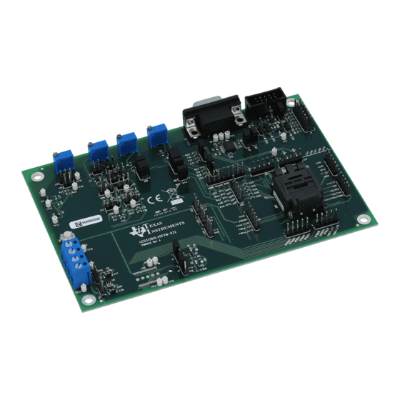
- Page 2 Description The UCD3138OL40EVM-032 is an EVM board used to facilitate the evaluation on the UCD3138RHA digital power controller. This EVM provides hardware needed to evaluate UCD3138 40-pin device. All pins of UCD3138RHA are accessible through header connections, including all GPIO pins, ADC12 pins, front end pins, DPWM pins, and Fault pins, etc.
- Page 3 Digital ground DGND Operation Environment Operating temperature range Natural convection °C Mechanical Characteristics Dimensions Width inches Length Component height Firmware for Testing Filename PWR032_UART0.x0 PWR032_Test_2.x0 SLUUA80 – January 2013 Using the UCD3138OL40EVM-032 Submit Documentation Feedback Copyright © 2013, Texas Instruments Incorporated...
- Page 4 Schematics www.ti.com Schematics Figure 1. UCD3138OL40EVM-032 Schematics (socket) 1 of 9 Using the UCD3138OL40EVM-032 SLUUA80 – January 2013 Submit Documentation Feedback Copyright © 2013, Texas Instruments Incorporated...
- Page 5 Schematics www.ti.com Figure 2. UCD3138OL40EVM-032 Schematics (headers) 2 of 9 SLUUA80 – January 2013 Using the UCD3138OL40EVM-032 Submit Documentation Feedback Copyright © 2013, Texas Instruments Incorporated...
- Page 6 AD01 AD00 [1,2] [1,2] AD01S AD00S 1000pF 1000pF AGND AGND 22.6k 1000pF 44.2k 1000pF AGND AGND Figure 3. UCD3138OL64EVM-031 Schematics (filters) 3 of 9 Using the UCD3138OL40EVM-032 SLUUA80 – January 2013 Submit Documentation Feedback Copyright © 2013, Texas Instruments Incorporated...
- Page 7 Schematics www.ti.com Figure 4. UCD3138OL40EVM-032 Schematics (bias and LEDs) 4 of 9 SLUUA80 – January 2013 Using the UCD3138OL40EVM-032 Submit Documentation Feedback Copyright © 2013, Texas Instruments Incorporated...
- Page 8 Schematics www.ti.com Figure 5. UCD3138OL40EVM-032 Schematics (UART and JTAG) 5 of 9 Using the UCD3138OL40EVM-032 SLUUA80 – January 2013 Submit Documentation Feedback Copyright © 2013, Texas Instruments Incorporated...
- Page 9 Schematics www.ti.com Figure 6. UCD3138OL40EVM-032 Schematics (PMBus) 6 of 9 SLUUA80 – January 2013 Using the UCD3138OL40EVM-032 Submit Documentation Feedback Copyright © 2013, Texas Instruments Incorporated...
- Page 10 DPWM2A [1,2,5] FLTR-DPWM2 DPWM2B [1,2,5] 1000pF 1000pF DGND DPWM3A [1,2,5] FLTR-DPWM3 DPWM3B [1,2,5] 1000pF 1000pF DGND Figure 7. UCD3138OL40EVM-032 Schematics (DPWM) 7 of 9 Using the UCD3138OL40EVM-032 SLUUA80 – January 2013 Submit Documentation Feedback Copyright © 2013, Texas Instruments Incorporated...
- Page 11 V33A [1,2,4,8] AD01S [3] 0.1uF AD03S [3] AD13S [3] OPA376AIDBVT 0.1uF AGND AGND AGND Figure 8. UCD3138OL40EVM-032 Schematics (EADC and ADC12) 8 of 9 SLUUA80 – January 2013 Using the UCD3138OL40EVM-032 Submit Documentation Feedback Copyright © 2013, Texas Instruments Incorporated...
- Page 12 Schematics www.ti.com Figure 9. UCD3138OL40EVM-032 Schematics (miscellaneous) 9 of 9 Using the UCD3138OL40EVM-032 SLUUA80 – January 2013 Submit Documentation Feedback Copyright © 2013, Texas Instruments Incorporated...
- Page 13 Microsoft Windows XP (32-bit), or Vista (32-bit), or Windows 7 (32-bit). USB-to-GPIO Interface Adapter This adapter is to establish the communication between the control card UCC3138OL40EVM-032 and the PC computer through the PMBus and the GUI, Texas Instruments Fusion Digital Power Designer.
- Page 14 Then click “Exit Program”. 6.1.3 Launch UCD3138 Device GUI The GUI for UCD3138OL40EVM-032 board can be launched through the below steps: 1. Click the window “start”. 2. click “All Programs”. 3. Click “Texas Instruments Fusion Digital Power Designer”.
- Page 15 6.2.1 Setup Overview Shown below in Figure 12 is the connection between UCD3138OL40EVM-032 and the personal computer through USB-to-GPIO interface adapter. USB Adapter Connection • Connect one end of the ribbon cable to the EVM, and connect the other end to the USB interface adapter.
- Page 16 Equipment Setup www.ti.com Figure 13. UCD31xx Device GUI Figure 14. Firmware Code Downloading Using the UCD3138OL40EVM-032 SLUUA80 – January 2013 Submit Documentation Feedback Copyright © 2013, Texas Instruments Incorporated...
- Page 17 Equipment Setup www.ti.com List of Test Points Table 2. UCD3138OL40EVM-032 Test Point Functions TEST POINTS NAME DESCRIPTION UART J4-2 UART transmitting UART J4-3 UART receiving UART GND DGND J38-1 DGND FLTR-DPWM2 DPWM2 front end connection FLTR-DPWM3 DPWM3 front end connection...
- Page 18 Test Procedure www.ti.com Test Procedure Download Firmware Codes to UCD3138OL40EVM-032 Set up the EVM connection based on Figure 1. Set up the EVM connection based on Figure 12. The LED of USB adapter is lighted up. 2. Use provided jumper jump across J39. The LED of the EVM is lighted on.
- Page 19 2), J13(1 and 2, 3 and 4, 5 and 6), J18(1 and 2, 3 and 4, 5 and 6). Figure 16. Location of Jumpers in Use SLUUA80 – January 2013 Using the UCD3138OL40EVM-032 Submit Documentation Feedback Copyright © 2013, Texas Instruments Incorporated...
- Page 20 “PWR032_UART0.x0”. Figure 17. Execution Result of Example Test Equipment Shutdown 1. Exit the GUI and UART. 2. Disconnect the cables. Using the UCD3138OL40EVM-032 SLUUA80 – January 2013 Submit Documentation Feedback Copyright © 2013, Texas Instruments Incorporated...
- Page 21 PCB dimensions: L x W = 6.0 inch x 4.0 inch, PCB material: FR4 or compatible, four layers and 1-oz copper on each layer. Figure 18. UCD3138OL40EVM-032 Top Layer Assembly Drawing (top view) Figure 19. UCD3138OL40EVM-032 Bottom Assembly Drawing (bottom view) SLUUA80 –...
- Page 22 EVM Assembly Drawing and PCB Layout www.ti.com Figure 20. UCD3138OL40EVM-032Top Copper (top view) Figure 21. UCD3138OL40EVM-032 Internal Layer 1 (top view) Using the UCD3138OL40EVM-032 SLUUA80 – January 2013 Submit Documentation Feedback Copyright © 2013, Texas Instruments Incorporated...
- Page 23 EVM Assembly Drawing and PCB Layout www.ti.com Figure 22. UCD3138OL40EVM-032 Internal Layer 2 (top view) Figure 23. UCD3138OL40EVM-032 Bottom Copper (top view) SLUUA80 – January 2013 Using the UCD3138OL40EVM-032 Submit Documentation Feedback Copyright © 2013, Texas Instruments Incorporated...
- Page 24 List of Materials www.ti.com List of Materials The EVM components list according to the schematics shown in Figure 1 Figure Table 3. UCD3138OL40EVM-032 List of Materials REFDES DESCRIPTION PART NUMBER C1, C2, C3, Capacitor, ceramic, 50 V, X7R, 10%, 0.1 µF, 0603...
- Page 25 List of Materials www.ti.com Table 3. UCD3138OL40EVM-032 List of Materials (continued) REFDES DESCRIPTION PART NUMBER R1, R11 Resistor, chip, 1/10 W, 1%, 100 Ω, 0805 R12, R13, R14, Resistor, chip, 1/16 W, 5%, 33 Ω, 0603 R15, R16, R17, Potentiometer, 3/8 cermet, single turn, right angle, 20...
- Page 26 Select “Remove All” to remove the existing configurations; then select “ARM7 SIMULATOR BIG ENDIAN” as shown in Figure 24, Click “ADD” and then “Save & Quit” for UCD3138 device. Summary of Using Code Composer Studio v3.3 SLUUA80 – January 2013 Submit Documentation Feedback Copyright © 2013, Texas Instruments Incorporated...
- Page 27 “Cyclone.out”, and the file of “Cyclone.x0” is saved inside the folder where “Cyclone.pjt” is saved. Figure 25. Open a Project File “Cyclone.pjt” – Initial Open SLUUA80 – January 2013 Summary of Using Code Composer Studio v3.3 Submit Documentation Feedback Copyright © 2013, Texas Instruments Incorporated...
- Page 28 Figure 26. Open a Project File “Cyclone.pjt” – Build Options and Linker Tab Figure 27. Open a Project File “Cyclone.pjt”- Build Options and General Tab Summary of Using Code Composer Studio v3.3 SLUUA80 – January 2013 Submit Documentation Feedback Copyright © 2013, Texas Instruments Incorporated...
- Page 29 6. TI Application Manual, UCD3138 ARM and Digital System Programmer’s Manual, Texas Instruments Literature Number SLUU994 7. UCD3138 Isolated Power Fusion GUI User Guide (please contact SLUUA80 – January 2013 Summary of Using Code Composer Studio v3.3 Submit Documentation Feedback Copyright © 2013, Texas Instruments Incorporated...
- Page 30 Any exceptions to this are strictly prohibited and unauthorized by Texas Instruments unless user has obtained appropriate experimental/development licenses from local regulatory authorities, which is responsibility of user including its acceptable authorization.
- Page 31 FCC Interference Statement for Class B EVM devices This equipment has been tested and found to comply with the limits for a Class B digital device, pursuant to part 15 of the FCC Rules. These limits are designed to provide reasonable protection against harmful interference in a residential installation. This equipment generates, uses and can radiate radio frequency energy and, if not installed and used in accordance with the instructions, may cause harmful interference to radio communications.
- Page 32 Also, please do not transfer this product, unless you give the same notice above to the transferee. Please note that if you could not follow the instructions above, you will be subject to penalties of Radio Law of Japan. Texas Instruments Japan Limited (address) 24-1, Nishi-Shinjuku 6 chome, Shinjuku-ku, Tokyo, Japan http://www.tij.co.jp...
- Page 33 EVALUATION BOARD/KIT/MODULE (EVM) WARNINGS, RESTRICTIONS AND DISCLAIMERS For Feasibility Evaluation Only, in Laboratory/Development Environments. Unless otherwise indicated, this EVM is not a finished electrical equipment and not intended for consumer use. It is intended solely for use for preliminary feasibility evaluation in laboratory/development environments by technically qualified electronics experts who are familiar with the dangers and application risks associated with handling electrical mechanical components, systems and subsystems.
- Page 34 • Products with "RoHS Exempt" under this column are EU RoHS exempt by using an applicable exemption(s). As of August 2010 to make identification of RoHS compliant EVMs easier, TI has provided labels on the outer EVM. Mailing Address: Texas Instruments, Post Office Box 655303, Dallas, Texas 75265 Copyright © 2013, Texas Instruments Incorporated...
- Page 35 STANDARD TERMS AND CONDITIONS FOR EVALUATION MODULES Delivery: TI delivers TI evaluation boards, kits, or modules, including any accompanying demonstration software, components, or documentation (collectively, an “EVM” or “EVMs”) to the User (“User”) in accordance with the terms and conditions set forth herein. Acceptance of the EVM is expressly subject to the following terms and conditions.
- Page 36 FCC Interference Statement for Class B EVM devices NOTE: This equipment has been tested and found to comply with the limits for a Class B digital device, pursuant to part 15 of the FCC Rules. These limits are designed to provide reasonable protection against harmful interference in a residential installation.
- Page 37 【無線電波を送信する製品の開発キットをお使いになる際の注意事項】 開発キットの中には技術基準適合証明を受けて いないものがあります。 技術適合証明を受けていないもののご使用に際しては、電波法遵守のため、以下のいずれかの 措置を取っていただく必要がありますのでご注意ください。 1. 電波法施行規則第6条第1項第1号に基づく平成18年3月28日総務省告示第173号で定められた電波暗室等の試験設備でご使用 いただく。 2. 実験局の免許を取得後ご使用いただく。 3. 技術基準適合証明を取得後ご使用いただく。 なお、本製品は、上記の「ご使用にあたっての注意」を譲渡先、移転先に通知しない限り、譲渡、移転できないものとします。 上記を遵守頂けない場合は、電波法の罰則が適用される可能性があることをご留意ください。 日本テキサス・イ ンスツルメンツ株式会社 東京都新宿区西新宿6丁目24番1号 西新宿三井ビル 3.3.3 Notice for EVMs for Power Line Communication: Please see http://www.tij.co.jp/lsds/ti_ja/general/eStore/notice_02.page 電力線搬送波通信についての開発キットをお使いになる際の注意事項については、次のところをご覧くださ い。http://www.tij.co.jp/lsds/ti_ja/general/eStore/notice_02.page SPACER EVM Use Restrictions and Warnings: 4.1 EVMS ARE NOT FOR USE IN FUNCTIONAL SAFETY AND/OR SAFETY CRITICAL EVALUATIONS, INCLUDING BUT NOT LIMITED TO EVALUATIONS OF LIFE SUPPORT APPLICATIONS.
- Page 38 Notwithstanding the foregoing, any judgment may be enforced in any United States or foreign court, and TI may seek injunctive relief in any United States or foreign court. Mailing Address: Texas Instruments, Post Office Box 655303, Dallas, Texas 75265 Copyright © 2015, Texas Instruments Incorporated...
- Page 39 IMPORTANT NOTICE Texas Instruments Incorporated and its subsidiaries (TI) reserve the right to make corrections, enhancements, improvements and other changes to its semiconductor products and services per JESD46, latest issue, and to discontinue any product or service per JESD48, latest issue.
- Page 40 Mouser Electronics Authorized Distributor Click to View Pricing, Inventory, Delivery & Lifecycle Information: Texas Instruments UCD3138OL40EVM-032...
Need help?
Do you have a question about the UCD3138OL40EVM-032 and is the answer not in the manual?
Questions and answers