
Subscribe to Our Youtube Channel
Related Manuals for Texas Instruments UCD3138LLCEVM-028


Summary of Contents for Texas Instruments UCD3138LLCEVM-028
- Page 1 Using the UCD3138LLCEVM-028 User's Guide Literature Number: SLUU979A August 2012 – Revised July 2013...
- Page 2 Any other use and/or application are strictly prohibited by Texas Instruments. If you are not suitably qualified, you should immediately stop from further use of the HV EVM.
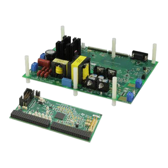
- Page 3 Converter Introduction This EVM, UCD3138LLCEVM-028 is to help evaluate the UCD3138 64-pin digital control device in an off- line power converter application and then to aid in its design. The EVM is a standalone LLC resonant half- bridge DC-to-DC power converter. The EVM is used together with its control card, UCD3138CC64EVM- 030, also an EVM on which is placed UCD3138RGC.
- Page 4 UCD3138CC64EVM-030 board. The UCD3138CC64EVM-030 is a daughter card with preloaded firmware that provides the required control functions for an LLC converter. For details of the firmware please contact TI. UCD3138LLCEVM-028 accepts a DC input from 350 V to 400 V...
- Page 5 Performance Specifications www.ti.com Performance Specifications Table 1. UCD3138LLCEVM-028 Performance Specifications PARAMETER TEST CONDITIONS UNITS Input Characteristics Voltage operation range Input UVLO On Input UVLO Off Input current Input = 350 V , full load = 29 A Input current Input = 380 V...
- Page 6 Schematics www.ti.com Schematics Figure 1. UCD3138LLCEVM-028 Schematic (image 1 of 2) Digitally Controlled LLC Resonant Half-Bridge DC-DC Converter SLUU979A – August 2012 – Revised July 2013 Submit Documentation Feedback Copyright © 2012–2013, Texas Instruments Incorporated...
- Page 7 Schematics www.ti.com Figure 2. UCD3138PFCEVM-026 Schematic (image 2 of 2) SLUU979A – August 2012 – Revised July 2013 Digitally Controlled LLC Resonant Half-Bridge DC-DC Converter Submit Documentation Feedback Copyright © 2012–2013, Texas Instruments Incorporated...
- Page 8 Schematics www.ti.com Figure 3. UCD3138CC64EVM-030 Schematic (image 1 of 2) Digitally Controlled LLC Resonant Half-Bridge DC-DC Converter SLUU979A – August 2012 – Revised July 2013 Submit Documentation Feedback Copyright © 2012–2013, Texas Instruments Incorporated...
- Page 9 6 NC 5 FB/NC 0.1uF 10uF 3.3VD DGND DGND Figure 4. UCD3138CC64EVM-030 Schematic (image 2 of 2) SLUU979A – August 2012 – Revised July 2013 Digitally Controlled LLC Resonant Half-Bridge DC-DC Converter Submit Documentation Feedback Copyright © 2012–2013, Texas Instruments Incorporated...
- Page 10 8 feet (a four foot input and a four foot return). Recommended Test Setup UART 1 (J5) Figure 5. UCD3138LLCEVM-028 Recommended Test Set Up Digitally Controlled LLC Resonant Half-Bridge DC-DC Converter SLUU979A – August 2012 – Revised July 2013 Submit Documentation Feedback Copyright ©...
- Page 11 Test Setup www.ti.com Figure 6. Orientation of Board UCD3138CC64EVM-030 on Board UCD3138LLCEVM-028 SLUU979A – August 2012 – Revised July 2013 Digitally Controlled LLC Resonant Half-Bridge DC-DC Converter Submit Documentation Feedback Copyright © 2012–2013, Texas Instruments Incorporated...
- Page 12 Reserved to an input fuse substitution Output_P Output voltage positive terminal Output_N Output voltage return terminal Digitally Controlled LLC Resonant Half-Bridge DC-DC Converter SLUU979A – August 2012 – Revised July 2013 Submit Documentation Feedback Copyright © 2012–2013, Texas Instruments Incorporated...
- Page 13 USB-TO-GPIO. For this measurement, the UCD3138LLCEVM-028 and UCD3138CC64EVM-030 boards are needed. 4. First install the UCD3138CC64EVM-030 board onto the UCD3138LLCEVM-028. Care must be taken with the alignment and orientation of the two boards, or damage may occur. Refer to Figure 6 UCD3138PFCEVM-030 board orientation.
- Page 14 Performance Data and Typical Characteristic Curves www.ti.com Performance Data and Typical Characteristic Curves Figure 7 through Figure 20 present typical performance curves for UCD3138LLCEVM-028. Efficiency 95.0% 90.0% 400Vdc 85.0% 380Vdc 350Vdc 80.0% Load Current (A) Figure 7. UCD3138LLCEVM-028 Efficiency Load Regulation 12.300...
- Page 15 SR2, A/div, Ch3 = V of Q7, Ch4 = V ripple) Ch4 = V of SR3) SLUU979A – August 2012 – Revised July 2013 Digitally Controlled LLC Resonant Half-Bridge DC-DC Converter Submit Documentation Feedback Copyright © 2012–2013, Texas Instruments Incorporated...
- Page 16 Figure 14. Output Voltage Ripple 380 V and Full Figure 15. Output Voltage Ripple 380 V and Half Load Load Digitally Controlled LLC Resonant Half-Bridge DC-DC Converter SLUU979A – August 2012 – Revised July 2013 Submit Documentation Feedback Copyright © 2012–2013, Texas Instruments Incorporated...
- Page 17 30 A Before OCP Latch-Off Shutdown (Ch1 = V of Q7, Ch2 = current of resonant network, Ch3 = V ripple) SLUU979A – August 2012 – Revised July 2013 Digitally Controlled LLC Resonant Half-Bridge DC-DC Converter Submit Documentation Feedback Copyright © 2012–2013, Texas Instruments Incorporated...
- Page 18 F - Frequency - kHz Gain Phase Figure 20. Control Loop Bode Plots at 400 V and Full Load Digitally Controlled LLC Resonant Half-Bridge DC-DC Converter SLUU979A – August 2012 – Revised July 2013 Submit Documentation Feedback Copyright © 2012–2013, Texas Instruments Incorporated...
- Page 19 PCB dimensions: L x W = 8.0 inch x 6.0 inch, PCB material: FR4 or compatible, four layers and 2-ounce copper on each layer Figure 21. UCD3138LLCEVM-028 Top Layer Assembly Drawing (top view) Figure 22. UCD3138LLCEVM-028 Bottom Assembly Drawing (bottom view) SLUU979A –...
- Page 20 EVM Assembly Drawing and PCB layout www.ti.com Figure 23. UCD3138LLCEVM-028 Top Copper (top view) Figure 24. UCD3138LLCEVM-028 Internal Layer 1 (top view) Digitally Controlled LLC Resonant Half-Bridge DC-DC Converter SLUU979A – August 2012 – Revised July 2013 Submit Documentation Feedback...
- Page 21 EVM Assembly Drawing and PCB layout www.ti.com Figure 25. UCD3138LLCEVM-028 Internal Layer 2 (top view) Figure 26. UCD3138LLCEVM-028 Bottom Copper (top view) SLUU979A – August 2012 – Revised July 2013 Digitally Controlled LLC Resonant Half-Bridge DC-DC Converter Submit Documentation Feedback...
- Page 22 List of Materials Component list based on Figure 1 Figure 2 Table 4. UCD3138LLCEVM-028 List of Materials REF DES DESCRIPTION PART NUMBER C1, C2, C4, C5, C6, Capacitor, ceramic, 16 V, X7R, 10%, 0.1 µF, 0603 C8, C11, C12, C21,...
- Page 23 List of Materials www.ti.com Table 4. UCD3138LLCEVM-028 List of Materials (continued) REF DES DESCRIPTION PART NUMBER Header, male 2 pin, 100-millimeter spacing, 0.100 PEC02SAAN Sullins inch x 2 inch Header, male 2 x 3 pin, 100-millimeter spacing, open, PEC03DAAN Sullins 0.20 inch x 0.30 inch...
- Page 24 References www.ti.com Table 4. UCD3138LLCEVM-028 List of Materials (continued) REF DES DESCRIPTION PART NUMBER Module, 5W, auxiliary bias PS, PCB assembly, 1.200 PWR050 inch x 2.200 inch N+1 and Oring Power Rail Controller, open, TSSOP- TPS2411PW High Input Voltage, Micropower, 3.2 µA at 80 mA TPS715A33DRBR LDO, 3.3 V, QFN-8...
- Page 25 Any exceptions to this are strictly prohibited and unauthorized by Texas Instruments unless user has obtained appropriate experimental/development licenses from local regulatory authorities, which is responsibility of user including its acceptable authorization.
- Page 26 FCC Interference Statement for Class B EVM devices This equipment has been tested and found to comply with the limits for a Class B digital device, pursuant to part 15 of the FCC Rules. These limits are designed to provide reasonable protection against harmful interference in a residential installation. This equipment generates, uses and can radiate radio frequency energy and, if not installed and used in accordance with the instructions, may cause harmful interference to radio communications.
- Page 27 Also, please do not transfer this product, unless you give the same notice above to the transferee. Please note that if you could not follow the instructions above, you will be subject to penalties of Radio Law of Japan. Texas Instruments Japan Limited (address) 24-1, Nishi-Shinjuku 6 chome, Shinjuku-ku, Tokyo, Japan http://www.tij.co.jp...
- Page 28 FDA Class III or similar classification, then you must specifically notify TI of such intent and enter into a separate Assurance and Indemnity Agreement. Mailing Address: Texas Instruments, Post Office Box 655303, Dallas, Texas 75265 Copyright © 2013, Texas Instruments Incorporated...
- Page 29 IMPORTANT NOTICE Texas Instruments Incorporated and its subsidiaries (TI) reserve the right to make corrections, enhancements, improvements and other changes to its semiconductor products and services per JESD46, latest issue, and to discontinue any product or service per JESD48, latest issue.
Need help?
Do you have a question about the UCD3138LLCEVM-028 and is the answer not in the manual?
Questions and answers