
Related Manuals for Tescom T-102


Summary of Contents for Tescom T-102
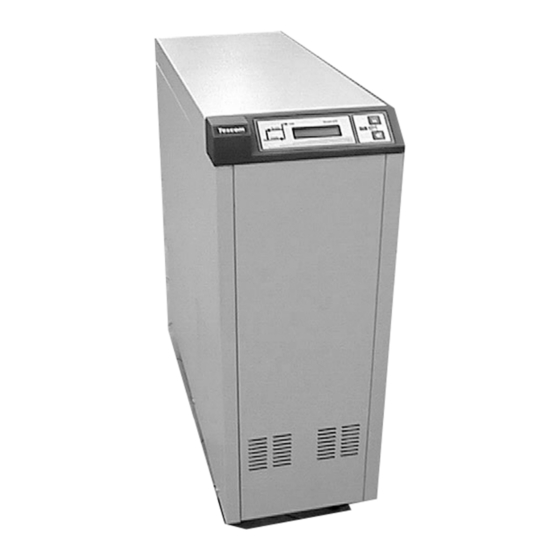
- Page 1 T-100 SERIES UNINTERRUPTIBLE POWER SUPPLIES ( 1 Phase Input & Output ) T-102 2 kVA T-103 3 kVA T-106 6 kVA T-107 7,5 kVA T-110 10 kVA T-115 15 kVA USER MANUAL...
-
Page 3: Table Of Contents
CONTENTS SAFETY .................. 2 INTRODUCTION ..............3 2.1 System Description............... 3 2.2 Technical Specifications ............... 5 III. INSTALLATION ..............7 3.1 Unpacking ..................7 3.2 Location Selection ................ 7 3.3 Cable Connections ............... 7 3.3.1 2-3 kVA ................8 3.3.2 5-6-7,5-10-15 kVA .............. 8 3.4 Start-Up .................. -
Page 5: Safety
T-100 Series UPS User Manual I. SAFETY This manual contains important instructions for T-100 series UPS that should be followed during installation and maintenance. IMPORTANT NOTICES 1. Read instructions carefully before operating the UPS 2. All warnings in the manual should be adhered to. 3. -
Page 6: Introduction
T-100 Series UPS User Manual II. INTRODUCTION Thank you for selecting this uninterruptible power supply (UPS). To choose the T-100 series as your equipment protector was a wise investment. It includes many features to protect your critical equipments. The T-100 series UPS system is connected between mains and critical loads, such as computer systems, telecommunication systems, computerized instruments etc. - Page 7 T-100 Series UPS User Manual Mechanical Transfer Switch Static Transfer Switch Static By-Pass Input Output Inverter Rectifier Battery Group Battery Charger Figure 2.1 UPS Block Diagram Rectifier : The first stage of the UPS. It supplies the DC bus voltage, which is necessary for operating the inverter by rectifying line voltage.
-
Page 8: Technical Specifications
T-100 Series UPS User Manual 2.2 Technical Specifications T-102 T-103 T-106 T-107 T-110 T-115 Power 2 kVA 3 kVA 6 kVA 7,5 kVA 10 kVA 15 kVA Power Factor >=0,9 Automatic Battery Test Alarm Relays RS 232 INPUT Input Voltage... - Page 9 T-100 Series UPS User Manual DB9 Port On-Off Switch Main Switch Output Output Fuse (F4) Input External battery socket 2-3 kVA DB9 Port Main Switch AC Output PK1 On-Off Switch UPS electrical connections 6 - 7,5 kVA 10 kVA DB9 Port AC Output PK1 On-Off Switch...
-
Page 10: Installation
UPS. 2. Carefully open the carton and take the UPS out. 3. Retain the carton and packing material for future use. Reverse line polarity indicator Unit package contents : T-102, T-103 T-106, T-107, T-110 T-115 User Manual Guarantee Certificate... -
Page 11: Kva
T-100 Series UPS User Manual The safety earth cable must be connected to the earth bus bar and bonded to each cabinet in the system. All cabinets should be earthed in accordance with local regulations. The UPS itself has no effect on the earthing quality i.e. it doesn’t change the unwanted voltage difference between the earth and neutral lines. -
Page 12: Start-Up
T-100 Series UPS User Manual 3.4 Start-Up 1. Turn on the Main Switch on the rear panel. (In this case, there is line voltage at the output and battery charger board is active) 2. Turn the On-Off Switch PK1 on the rear panel to "1" position. In a few seconds the cooling fan will start to operate, then the red LED "by-pass"... -
Page 13: Operating Procedure
T-100 Series UPS User Manual IV. OPERATING PROCEDURE 4.1 Turn On procedure 1. Turn on the Main Switch on the rear panel to "1" position. (There is line voltage at the output.) 2. Turn on the On-Off Switch PK1 on the rear panel to the "1" position. Turn on the power switches on your critical load after the "Inverter"... -
Page 14: First Message (Up) Line Of The Lcd
T-100 Series UPS User Manual (2) Display Select Status Indicators (1) Sound On-Off Button Figure 4.1 Control Panel 4.4.2 First message (Up) line of the LCD The percentage of the load connected to the UPS output during this message LOAD the sound button enables/disables sound alarm. -
Page 15: Second Message Line Of The Lcd
T-100 Series UPS User Manual 4.4.3 Second message line of the LCD VERSION XXXX Micro controller software version of the UPS. This message shown that there is a problem of the static bypass system, BYPASS FAILURE please call for service. “INVERTER FAILURE”... -
Page 16: Optional Equipment
T-100 Series UPS User Manual V. OPTIONAL EQUIPMENT 5.1 Software Options The UPS can send digital data (optional) to the computer thought the RS232 port. No additional card is needed. It also has two alarm relays: Line failure and battery low. Computer systems require time to perform an orderly shutdown, without corrupting or losing data In an extended power failure, a computer system protected by a UPS eventually will lose power when the battery is exhausted. -
Page 17: Snmp Module
T-100 Series UPS User Manual 5.2 SNMP Module Using the SNMP module, your UPS is seen as a network device in your WAN or LAN applications, and with this way it can be monitored more than one UPS’s connected to your network through SNMPVIEW Software supplied with the module or it is possible to monitor the UPS through an Internet Browser. -
Page 18: Remote Monitoring Panel (Rmp)
T-100 Series UPS User Manual 5.4 Remote monitoring panel (RMP) You can see UPS status and parameters without using a computer up to 200 meters ( via RS485 interface). And you can connect more than one remote panel in cascade for monitoring your UPS system from several different locations at the same time. - Page 19 T-100 Series UPS User Manual...
- Page 20 T-100 Series UPS User Manual ( T-MON ) COM1 Connection Diagram Of The RMP...
-
Page 21: Customer Service
T-100 Series UPS User Manual VI. CUSTOMER SERVICE WARNING! There are no customer serviceable components inside. DO NOT open the cover or attempt to service the unit. High voltage may remain when the unit is shut down. Unauthorized service will void the warranty and could cause serious injury. 6.1 Maintenance The unit is designed for easy maintenance. -
Page 22: Limited Warranty
T-100 Series UPS User Manual VII. LIMITED WARRANTY The UPS is warranted against all defects in workmanship and materials under normal use for a period of one ( ) year from the date of shipment to the original user. The conditions of this warranty and the extent of responsibility of ………………………………………………………………………………………………………………………….. - Page 23 AGKK3772 02/2011...
Need help?
Do you have a question about the T-102 and is the answer not in the manual?
Questions and answers
How do I connect solar to my tescom online ups