Table of Contents
Advertisement
Quick Links
EVK-NINA-B4
Evaluation kit for NINA-B4 modules
User guide
Abstract
This document describes how to set up the EVK-NINA-B4 evaluation kit to evaluate NINA-B4 series
standalone Bluetooth
and testing the development capabilities included in the evaluation board.
UBX-19054587 - R04
C1 - Public
®
5.1 low energy modules. It also describes the different options for debugging
www.u-blox.com
Advertisement
Table of Contents

Subscribe to Our Youtube Channel
Related Manuals for Ublox EVK-NINA-B400


Summary of Contents for Ublox EVK-NINA-B400
- Page 1 EVK-NINA-B4 Evaluation kit for NINA-B4 modules User guide Abstract This document describes how to set up the EVK-NINA-B4 evaluation kit to evaluate NINA-B4 series standalone Bluetooth ® 5.1 low energy modules. It also describes the different options for debugging and testing the development capabilities included in the evaluation board. UBX-19054587 - R04 C1 - Public www.u-blox.com...
-
Page 2: Document Information
Revision and date 29-Jun-2021 Disclosure restriction C1 - Public This document applies to the following products: Product name EVK-NINA-B400 EVK-NINA-B410 EVK-NINA-B410DF EVK-NINA-B406 EVK-NINA-B416 u-blox or third parties may hold intellectual property rights in the products, names, logos and designs included in this document. -
Page 3: Table Of Contents
EVK-NINA-B4 - User guide Contents Document information ..........................2 Contents ............................... 3 Quick start guide ..........................5 Product description ..........................6 2.1 Overview ................................ 6 2.2 Kit includes ..............................7 2.3 Key features ..............................7 2.4 EVK-NINA-B4 block diagram ........................8 2.5 Connectors .............................. - Page 4 EVK-NINA-B4 - User guide Appendix ..............................34 Schematics ............................34 Glossary .............................. 38 Related documents ..........................39 Revision history ............................39 Contact ............................... 40 UBX-19054587 - R04 Contents Page 4 of 40 C1 - Public...
-
Page 5: Quick Start Guide
EVK-NINA-B4 - User guide Quick start guide EVK-NINA-B4 software and documentation is available at www.u-blox.com/evk-search. Install s-center evaluation software s-center is a powerful and easy-to-use tool for evaluating, configuring, and testing u-blox short range modules. Running on Windows 10 operating systems, the software allows end users to assess and configure u-blox short range modules using the EVK. -
Page 6: Product Description
• EVK-NINA-B400, with open CPU NINA-B400 module and U.FL antenna connector for connecting to external antennas. The EVK-NINA-B400 is also used for evaluation of NINA-B401 module. • EVK-NINA-B410, with u-connect NINA-B410 module pre-flashed with u-connectXpress software or boot prepared for u-connectLocate software (EVK-NINA-B410DF), and U.FL antenna... -
Page 7: Kit Includes
2.2 Kit includes The EVK-NINA-B4 evaluation kit includes the following: • NINA-B4 evaluation board • 2.4 GHz antenna with U.FL connector (only in EVK-NINA-B400 and EVK-NINA-B410) • NFC antenna • USB cable 2.3 Key features •... -
Page 8: Evk-Nina-B4 Block Diagram
EVK-NINA-B4 - User guide 2x UART with HW flow control 2x I2C 1x I2S 1x PDM input 1x Quadrature decoder • EVK-NINA-B41x: support for u-connectXpress software • EVK-NINA-B40x: support for developing your own software on the Open CPU NINA-B4 module •... -
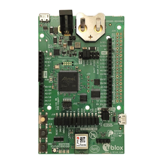
Page 9: Connectors
U.FL coaxial connector that can be used to connect antennas or RF equipment. This connector connector is only included in the EVK-NINA-B400/EVK-NINA-B410. Cortex Debug connector 10-pin, 50 mil pitch connector that can be used to connect external debuggers to the NINA-B4 module. -
Page 10: Setting Up The Evaluation Board
To use Bluetooth Low Energy on EVK-NINA-B410 and EVK-NINA-B416 boards, connect a 2.4 GHz antenna to the U.FL antenna connector. The EVK-NINA-B400 and EVK-NINA-B406 board variants include antennas on the NINA module. Plug in either an external power supply in the J5 connector or connect to a USB host with a USB cable attached to the J8 connector. -
Page 11: Evk-Nina-B40X
EVK-NINA-B4 - User guide 3.2.1.1 u-connectXpress software EVK-NINA-B41x is equipped with a NINA-B41x module that runs the u-connectXpress software. The software is preinstalled on the module. ☞ Go to the u-blox support webpage to obtain the latest available software. Instructions on reflashing the EVK-NINA-B4 can be found in the Software section of the NINA-B4 system integration manual [4]. -
Page 12: Using A Voltmeter
EVK-NINA-B4 - User guide Using a voltmeter The EVK board must be modified before module current can be measured with a voltmeter. To modify the board, solder a low resistance, high tolerance, 0402 sized resistor to the footprint labeled R6. This resistor replaces the jumper normally positioned between J22 pins - 1 and 3, and any current running through it produce a voltage across its terminals. -
Page 13: Using An External Power Supply Or Power Analyzer
EVK-NINA-B4 - User guide Using an external power supply or power analyzer Connect the terminals of the instrument to the EVK pins, as shown in Figure 5. An ampere meter can also be added in series. Since the external voltage of any connected instrument can never perfectly match the 3.3 V generated by the EVK, some small current leakage is apparent whenever the signal from the NINA module is connected to an EVK peripheral. -
Page 14: Board Configuration
EVK-NINA-B4 - User guide Board configuration 4.1 Powering options Power can be supplied to the board in any of the following ways: • Via any of the USB connectors, J8 or J16 • Using the power jack, J5 • Using the Arduino interface VIN or 5V pin, J1.8 or J1.5 •... - Page 15 EVK-NINA-B4 - User guide Sources Net names Targets DC/DC VDD_MCU Onboard 3.3 V PC communication converter 3V3_PI VBAT Raspberry Pi expansion board Battery VBAT_DIODE VDD_IO Battery with Board I/O power: protection diode Level shifters, LEDs etc. -.-- V Any power net VCC_IO NINA module power External supply...
- Page 16 EVK-NINA-B4 - User guide Connector Pin no. Schematic net Description Regulated 3.3 V net. This net is supplied by the board and will always be powered as long as a power source is connected. 3V3_PI Connects to the Raspberry Pi header’s (J14) 3V3 pins. If a Raspberry Pi is connected, this net must be unconnected to prevent back currents.
-
Page 17: Default Power Configuration, 3.3 V
EVK-NINA-B4 - User guide Default power configuration, 3.3 V This is the default power configuration for the evaluation board, and the jumpers are installed out-of-the-box with this power configuration. All board peripherals are powered up, the NINA module is directly supplied by the board, and everything is running at 3.3 V. J7: 7-8 J7: 9-10 J22: 2-4... -
Page 18: Battery Powered, 3-1.7 V
EVK-NINA-B4 - User guide Battery powered, 3–1.7 V When using a battery, Figure 10 shows the default configuration. The battery voltage is connected to VDD_NINA, which in turn, is connected to the NINA-B4 VCC supply. If needed, a jumper can be added to J22 pins - 2 and 4 to supply LEDs and other peripherals with power, as long as this does not exceed the maximum current rating of the battery. -
Page 19: Battery Powered With Protection Diode, 2.7-1.7 V
EVK-NINA-B4 - User guide Battery powered with protection diode, 2.7–1.7 V This use case is meant to protect the battery from current back surges. When using the NFC interface, there is a risk that the applied electromagnetic field can cause back surges on the module’s power supply lines that will typically damage a non-chargeable battery. -
Page 20: External Supply, 3.6-1.7 V
EVK-NINA-B4 - User guide External supply, 3.6–1.7 V When measuring current consumption or performing other NINA-B4 module characterization measurements, it can be useful to power the module with an external source such as a lab power supply. In such cases, all jumpers can be removed and the required supply nets can be fed externally by connecting to the pin headers. -
Page 21: Raspberry Pi Hat
EVK-NINA-B4 - User guide Raspberry Pi HAT When connecting a HAT to the Raspberry Pi interface, the following jumper configuration can be used. Depending on how the NINA module is to communicate with a test PC over USB or with the HAT, the VDD_MCU net could be left unpowered. - Page 22 EVK-NINA-B4 - User guide NINA Signal Jumper Headers J1 9 J1 9 Figure 14: Jumper headers J19 and J9 that are used to isolate specific NINA signals Connector Pin no. Schematic net name Description RESET_N NINA reset signal, active low RESET_N_I Connects to the Interface MCU’s reset line SWDIO...
-
Page 23: Connecting An External Antenna (Evk-Nina-B410Df)
EVK-NINA-B4 - User guide 4.3 Connecting an external antenna (EVK-NINA-B410DF) An antenna used for direction finding has many antenna elements that are controlled via an antenna switch. The antenna switch is controlled by several GPIOs on the EVK-NINA-B410DF. The antenna also needs to be fed with power and a ground connection from the EVK. -
Page 24: Interfaces And Peripherals
EVK-NINA-B4 - User guide Interfaces and peripherals 5.1 Buttons and LEDs Buttons and LEDs Reset Interface MCU LED User button Interface MCU LED User button Status LED TXD LED RXD LED RTS LED CTS LED DTR LED DSR LED Figure 15: Position of the push buttons and LEDs on the evaluation board Annotation Function Description... -
Page 25: Arduino Interface
EVK-NINA-B4 - User guide 5.2 Arduino interface The EVK-NINA-B4 includes a set of pin headers and mounting holes that are compatible with certain Arduino or Arduino inspired shields. Figure 16 shows the layout of the Arduino interface described in Table 12. See also Arduino shield compatibility for information about compatible shields for EVK-NINA-B4. - Page 26 EVK-NINA-B4 - User guide Conn. Arduino Description Schematic nRF52 Alternate functions and notes net name Analog input GPIO_25 P0.04 Analog function capable GPIO Analog input GPIO_24 P0.30 Analog function capable GPIO Analog input GPIO_27 P0.05 Analog function capable GPIO Analog input SWITCH_2/ P0.02 Analog function capable GPIO,...
-
Page 27: Arduino Shield Compatibility
EVK-NINA-B4 - User guide Arduino shield compatibility ☞ As EVK-NINA-B4 has an I/O voltage range of 1.7–3.6 V, it can only be used with shields that support an I/O voltage in this range. The EVK-NINA-B4 has a pinout that is compatible with some Arduino, or Arduino-inspired, shields. The characteristics of certain EVK pins demand that shields support the following features: •... - Page 28 EVK-NINA-B4 - User guide Figure 17 shows the layout of the Raspberry Pi interface described in Table 14. Three mounting holes can be used for increasing the mechanical stability. The two holes on each side of connector J14 are common to all Raspberry Pi boards, but the third one is only compatible with the Pi Zero boards. Raspberry Pi Interface J1 4 J1 4...
- Page 29 EVK-NINA-B4 - User guide Conn. Raspberry Description Schematic nRF52 Alternate functions and notes Pi pin net name Connected to 32Khz LPO clock. To connect GPIO 2 to J4 header instead of LPO clock, remove R66 and add R64 (0 Ω resistor) GPIO18 Digital I/O...
-
Page 30: Powering Considerations
EVK-NINA-B4 - User guide Powering considerations Two voltage nets are used in the Raspberry Pi interface, 3V3_PI and 5V. Both the 3V3_PI and 5V nets can be used to power HATs, but these nets should not be used when connecting to a Raspberry Pi. See also Raspberry Pi HAT. - Page 31 EVK-NINA-B4 - User guide Additional Interfaces External Flash UART U1 0 SPI_CS VDD_IO SPI_MISO GPIO_47 GPIO_49 SPI_CLK Trace SPI_MOSI UART U1 0 Debug and Trace Flash Memory Figure 18: Additional interfaces that require some soldering before use Connector Schematic net name nRF52 pin Description annotation...
-
Page 32: Extra Memory - External Flash
EVK-NINA-B4 - User guide Connector Schematic net name nRF52 pin Description annotation number Not connected TRACE_CLK/GPIO_45 P0.07 Parallell trace clock signal Not connected TRACE_D0/SWO/ P1.00 Serial trace data signal / Parallell trace data signal GPIO_8 Ground TRACE_D1/GPIO_46 P0.12 Parallell trace data signal Ground TRACE_D2/GPIO_32 P0.11... -
Page 33: Cpu Trace Interface
EVK-NINA-B4 - User guide CPU trace interface The Arm Cortex-M4Fprocessor in NINA-B4 modules supports tracing of CPU instructions through the 20-pin, 50 mil pitch, Cortex Debug + ETM connector. This extended connector has the same features as J12, but also accommodates instruction trace operations through the Embedded Trace Macrocell (ETM) of the Cortex-M4 microcontroller in the NINA-B4 module. -
Page 34: Appendix
EVK-NINA-B4 - User guide Appendix A Schematics UBX-19054587 - R04 Appendix Page 34 of 40 C1 - Public... - Page 35 EVK-NINA-B4 - User guide UBX-19054587 - R04 Appendix Page 35 of 40 C1 - Public...
- Page 36 EVK-NINA-B4 - User guide ☞ For the first prototype build (marked PT1) EVK-NINA-B3 schematic can be used as a reference. UBX-19054587 - R04 Appendix Page 36 of 40 C1 - Public...
- Page 37 EVK-NINA-B4 - User guide ☞ For the first prototype build (marked PT1) EVK-NINA-B3 schematic can be used as a reference. ☞ Pages 2 and 6 of the schematic are intentionally omitted. UBX-19054587 - R04 Appendix Page 37 of 40 C1 - Public...
-
Page 38: B Glossary
EVK-NINA-B4 - User guide B Glossary Abbreviation Definition Application programming interface Clear To send Evaluation kit Ground GPIO General-Purpose Input/Output Light-Emitting Diode Micro controller unit Mass storage device Near Field Communication U.FL Coaxial RF connector Universal serial bus Request To send Software development kit SOIC Small outline integrated circuit... -
Page 39: Related Documents
EVK-NINA-B4 - User guide Related documents [1] Arduino – https://www.arduino.cc [2] Raspberry Pi - https://www.raspberrypi.org/ [3] NINA-B4 data sheet, UBX-19049405 [4] NINA-B4 series system integration manual, UBX-19052230 [5] u-blox Short range AT commands manual, UBX-14044127 [6] SEGGER J-Link software - https://www.segger.com/jlink-software.html [7] u-connectXpress user guide, UBX-16024251... -
Page 40: Ubx-19054587 - R04
EVK-NINA-B4 - User guide Contact For complete contact information, visit us at www.u-blox.com. u-blox Offices North, Central and South America Headquarters Asia, Australia, Pacific Europe, Middle East, Africa u-blox America, Inc. u-blox Singapore Pte. Ltd. u-blox AG Phone: +1 703 483 3180 Phone: +65 6734 3811 E-mail:... - Page 41 X-ON Electronics Largest Supplier of Electrical and Electronic Components Click to view similar products for category: Bluetooth Development Tools - 802.15.1 Click to view products by manufacturer: U-Blox Other Similar products are found below : DA14580PRODTLKT 1628 SP14808ST MBH7BLZ02-EF-KIT FWM7BLZ20-EB-KIT SP14801-DUT SKY66111-21EK1 SECO-RSL10- TAG-GEVB 3026 MIKROE-2471 BLE-IOT-GEVB 450-0184 EKSHCNZXZ EVAL_PAN1026 EVAL_PAN1720 EVAL_PAN1740 2267 2479 2487 2633 STEVAL-IDB005V1D STEVAL-IDB001V1 MIKROE-2545 SIPKITSLF001 2995 STEVAL-IDB007V1M 2829 DFR0267 DFR0296 BM-70-CDB STEVAL-BTDP1 ACD52832 TEL0095 RN-4871-PICTAIL DA14695-00HQDEVKT-P DA14695-...
Need help?
Do you have a question about the EVK-NINA-B400 and is the answer not in the manual?
Questions and answers