Table of Contents
Advertisement
Quick Links
Advertisement
Table of Contents

Related Manuals for Viking Range FDBB


Summary of Contents for Viking Range FDBB
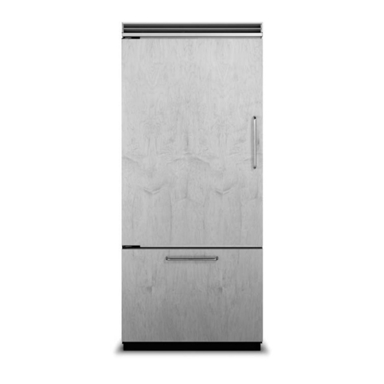
- Page 1 Installation Guide Custom Panel Built-in Bottom-Freezer Refrigerator...
-
Page 2: Table Of Contents
Table of Contents Warnings & Important Information ____________________________________________________________________3 Dimensions and Specifications (36”) __________________________________________________________________5 Cutout Dimensions (36”) ____________________________________________________________________________7 Anti-Tip Dimensions (36”) ___________________________________________________________________________8 Overlay Dimensions (36”) ____________________________________________________________________________9 Custom Grille Dimensions (36”) _____________________________________________________________________10 Cabinet Information _______________________________________________________________________________12 Custom Side Panel Dimensions _____________________________________________________________________13 Custom Panel General Information __________________________________________________________________14 Custom Door Panel Installation –... -
Page 3: Warnings & Important Information
IMPORTANT – Please Read and Follow • Make sure that incoming voltage is the same as Your safety and the safety of others is unit rating. An electric rating plate specifying very important. voltage, frequency, wattage, amperage, and We have provided many important safety phase is attached to the product. - Page 4 • The required use of a GFI is normally related to the location of a receptacle with respect to any significant sources of water or moisture. • Viking Range, LLC will NOT warranty any problems resulting from GFI outlets which are not installed properly or do not meet the requirements below.
-
Page 5: Dimensions And Specifications (36")
Dimensions (Bottom-Freezer) 36” Bottom-Freezer 3 5 ” ( 8 8 . 9 c 3 - 1 9 / 3 1 - 1 ( 9 . 1 2 ” / 2 ” 3 6 ” ( 3 . 8 ( 9 1 . - Page 6 Specifications (Bottom-Freezer) 36” Bottom-Freezer Description FDBB/CFDBB Overall width 36” (91.5 cm) Overall height (from bottom) 82-3/4” (210.2 cm) min. to 84-1/16” (213.5 cm) max. Overall depth (from rear) To front edge of side trim: 23-3/16” (58.9 cm) To front of top grille: 24” (61.0 cm) Cutout width 36”...
-
Page 7: Cutout Dimensions (36")
Cutout Dimensions (Bottom-Freezer) 36” Bottom-Freezer Electric Outlet Location 6 ” ( 1 5 . 2 c m ) 9 ” ( 2 2 . 9 c m ) 9 ” ( 2 2 . 9 c m ) 8 2 - 7 / 8 ”... -
Page 8: Anti-Tip Dimensions (36")
Anti-Tip Dimensions (Bottom-Freezer) 36” Bottom-Freezer Anti-Tip Location 7 9 - 3 ” 1 - 1 / 2 / 8 ” ( 2 0 1 . 6 c m ( 3 . 8 c ) m i n t o b o t t o m a n t i - t i p b... -
Page 9: Overlay Dimensions (36")
Overlay Dimensions (Bottom-Freezer) 36” Custom Panels ” 3 / 4 - 1 / ( 1 . 9 ( 8 9 4 ” . 5 c - 1 / ( 1 3 4 ” 0 . 2 t e : h i n 5 / 8 r n e S e e... -
Page 10: Custom Grille Dimensions (36")
Custom Grille Dimensions (Bottom-Freezer) 36” Custom Grille 1 / 2 ” ( 1 . 2 3 / 4 / 4 ” ” ( 1 . 9 2 - 3 i u s i u s i u s ( 6 . ”... - Page 11 Custom Grille Dimensions (Bottom-Freezer) Dual 36” Custom Grille 4 - 3 1 / 2 / 1 6 ( 1 . 2 ” ( 1 0 3/4” ” 1/8” 1/2” . 6 1 3 / 4 / 4 ” (1.90 cm) ”...
-
Page 12: Cabinet Information
Cabinet Information Custom panel models, (with 3/4” [1.9 cm], thick panels and custom handles locally supplied), fit flush in 25” (63.5 cm) deep (countertop depth) cabinet openings with no protrusion into room except custom handles Top View Wall 1/4” (.63 cm) space if 25”... -
Page 13: Custom Side Panel Dimensions
Custom Side Panel Dimensions 1” Z-Bracket (2.5 cm) 1/4” (0.6 cm) 4 ” - 3 / ( 5 5 3/4” (1.9 cm) End panel 4 ” - 3 / ( 5 5 ( 2 1 - 7 / 0 . 5 8 ”... -
Page 14: Custom Panel General Information
Custom Panel General Information Custom finishing options • Panel thickness must not exceed 1” (2.5 cm) • All installations must allow for the refrigerator on hinge side. Thicker panels will interfere with and freezer door to open a minimum of 90˚. door swing and clearance. - Page 15 Custom Door Panel Installation (cont.) x12 BTM x13 SxS, AFAR Attach “Z” bracket to the hinge side of custom panel. Push custom wood panel onto door. Attach bracket to the handle side of custom panel. Reinstall handle side door trim Slide custom wood panel to the hinge side, ensuring “Z”...
- Page 16 Custom Freezer Door Panel Installation (Bottom-Freezer cont.) Open freezer door. Remove door trim screws Remove bracket. and door trim with a phillips screwdriver. 2-1/16” 2-1/16” 2-1/16” 2-1/16” (5.2 cm) (5.2 cm) (5.2 cm) (5.2 cm) 1-11/16” 1-11/16” 1-11/16” 1-11/16” 1-11/16” 1-11/16”...
-
Page 17: Door Trim Insert
Install Door Trim Insert Use the roll of trim insert located in the drawer inside the unit to apply to the door trim. Bottom-Freezer Custom Panel Hinge Cutout (if required) 5 / 8 ” ( 1 . 6 3 ” ( 7 . -
Page 18: Custom Grille Installation
Custom Grille Installation Remove air grille center blade. Remove two 1/4” (0.6 cm) screws with a magnetic extended screwdriver at least 8” (20.3 cm) long. Pull air grille assembly forward. Remove 2 mounting brackets from the grille air assembly. - Page 19 Custom Grille Installation (cont.) Using eight screws removed from the mounting brackets, Insert custom air grille assembly. attach mounting brackets to the custom wood grille using predrilled pilot holes. (See grille overlay specifications for proper alignment and pilot hole placement.) Install two 1/4”...
-
Page 20: General Information
This appliance is equipped with a power supply • Viking Range, LLC is not responsible for cord having a 3-prong grounding plug. To property damage due to improper installation minimize possible shock hazard, the cord must or water connection. -
Page 21: Unpacking & Moving
General Information Unpacking unit • DO NOT use the self-piercing feature of a saddle valve. The hole made by the piercing lance is too 1. Remove top and bottom strap. small for the water flow rate required by the ice 2. -
Page 22: Installation
Installation Place unit in front of cutout. Pull the center grille louver up at an angle and pull out. Using an 8” (20.3 cm) magnetic nut driver, Remove grille assembly. remove the two 1/4” (0.6 cm) screws. -
Page 23: Hinge Adjustment
Hinge Adjustment Front of unit Remove four side screws and remove unit top. Loosen the four hinge screws. Adjust door. Retighten four hinge screws. Wall 2 x 4 Refrigerator Replace unit top and four side screws. Attach one 2 x 4 to wall stud (refer to dimensions page for exact location). - Page 24 Installation (cont.) Place unit within 3” of being flush with cabinets. Note: To avoid Carefully move unit until semi flush with cabinet cabinet damage, place cardboard between cabinets and unit. When (depending on unit). moving unit, DO NOT crimp, kink or crush water supply line. Flush water line by running two quarts of water Pull supply tubing forward under unit.
- Page 25 Hinge Adjustment (cont.) Screw Wall 2 x 4 Refrigerator Attach positive secure self-tapping bolts Lift unit off rollers to desired height to 2 x 4 using a 22” (55.6 cm) extension. and level unit using a 5/16” head wrench. Note: DO NOT use an electric device. Overtightening can cause damage.
-
Page 26: Kickplate Installation
Kickplate Installation Align holes on both ends of louvered panels Using a phillips screwdriver, attach the and insert screws. kickplate to the unit and adjust to desired height. Door Stop Adjustment (Bottom-Freezer) 120˚ 120˚ 120˚ 110˚ 110˚ 110˚ 90˚ Open refrigerator door so door stop and Remove shoulder screw and place shoulder screw are accessible. -
Page 27: Water Filter System Specifications
Water Filter System Specification and Performance Data Sheet This system has been tested according to NSF/ANSI 42/53 for reduction of the substances listed below. The concentration of the indicated substances in water entering the system was reduced to a concentration of less than or equal to the permissible limit for water leaving the system, as specified in NSF/ANSI 42/53.* (100% safety factors built-in for unmetered usage for health claims only.) NSF Specified... -
Page 28: Final Installation
Final Installation Replace top air grille. Using an 8” magnetic nut driver, replace the two 1/4” screws. Replace the center grille louver. Open door. The display should flash. Press “ACTIVATE CONTROLS” pad and close door. Note: There is a 6 minute delay before the unit starts. -
Page 29: Performance Checklist
Performance Checklist □ Verify cabinet size. □ Verify electrical supply and water supply (if applicable). □ Install anti-tip device(s) and verify unit is secure. □ Position unit in cutout, level at desired height and secure unit. □ Plug-in unit and verify operation. □... -
Page 30: Control Panels
Verify Operations Control Panels Bottom-Freezer FREEZER FREEZER REFRIGERATOR REFRIGERATOR MAX FRZ MAX FRZ MAX REF MAX REF DOOR OPEN DOOR OPEN ACTIVATE ACTIVATE FAST FAST ALARM ALARM DISPLAY DISPLAY HIGHER HIGHER LOWER LOWER CONTROLS CONTROLS TEMP TEMP TEMP TEMP COOL COOL FAST COOL FAST COOL... -
Page 31: Service & Registration
• Name of dealer from whom purchased Clearly describe the problem that you are having. If you are unable to obtain the name of an authorized service agency, or if you continue to have service problems, contact Viking Range, LLC at 1-888-(845-4641), or write to:... - Page 32 Viking Range, LLC 111 Front Street Greenwood, Mississippi 38930 USA (662) 455-1200 For product information, call 1-888-(845-4641) or visit our web site at brigade.ca (100115) F21419 EN...
Need help?
Do you have a question about the FDBB and is the answer not in the manual?
Questions and answers