
Related Manuals for Kyocera AK-730


Summary of Contents for Kyocera AK-730
- Page 1 All manuals and user guides at all-guides.com DF-770 AK-730 PH-7A/7C/7D SERVICE MANUAL Published in January 2011 843NC110 3NCSM060 First Edition...
- Page 2 All manuals and user guides at all-guides.com CAUTION RISK OF EXPLOSION IF BATTERY IS REPLACED BY AN INCORRECT TYPE. DISPOSE OF USED BATTERIES ACCORDING TO THE INSTRUCTIONS. It may be illegal to dispose of this battery into the municipal waste stream. Check with your local solid waste officials for details in your area for proper disposal.
- Page 3 All manuals and user guides at all-guides.com Revision history Revision Date Replaced pages Remarks...
- Page 4 All manuals and user guides at all-guides.com This page is intentionally left blank.
- Page 5 All manuals and user guides at all-guides.com Safety precautions This booklet provides safety warnings and precautions for our service personnel to ensure the safety of their customers, their machines as well as themselves during maintenance activities. Service personnel are advised to read this booklet carefully to familiarize themselves with the warnings and precautions described here before engaging in maintenance activities.
- Page 6 All manuals and user guides at all-guides.com Safety warnings and precautions Various symbols are used to protect our service personnel and customers from physical danger and to prevent damage to their property. These symbols are described below: DANGER: High risk of serious bodily injury or death may result from insufficient attention to or incorrect compliance with warning messages using this symbol.
- Page 7 All manuals and user guides at all-guides.com 1. Installation Precautions WARNING • Do not use a power supply with a voltage other than that specified. Avoid multiple connections to one outlet: they may cause fire or electric shock. When using an extension cable, always check that it is adequate for the rated current.
- Page 8 All manuals and user guides at all-guides.com 2. Precautions for Maintenance WARNING • Always remove the power plug from the wall outlet before starting machine disassembly....• Always follow the procedures for maintenance described in the service manual and other related brochures.
- Page 9 All manuals and user guides at all-guides.com • Do not remove the ozone filter, if any, from the copier except for routine replacement....... • Do not pull on the AC power cord or connector wires on high-voltage components when removing them;...
- Page 10 All manuals and user guides at all-guides.com This page is intentionally left blank.
-
Page 11: Table Of Contents
All manuals and user guides at all-guides.com 3NC/3NB/3NK CONTENTS 1-1 Specifications 1-1-1 Specifications ........................1-1-1 1-1-2 Parts names .......................... 1-1-2 (1) Document Finisher ......................1-1-2 (2) Bridge unit ........................1-1-3 1-1-3 Machine cross section ......................1-1-4 1-2 Installation 1-2-1 Installation environment......................1-2-1 1-2-2 Unpacking.......................... - Page 12 All manuals and user guides at all-guides.com 3NC/3NB/3NK (3) Scan to E-mail error codes ................... 1-4-109 1-4-7 Error codes ........................1-4-110 (1) Error code........................1-4-110 (2) Table of general classification ..................1-4-111 (2-1) U004XX error code table: Interrupted phase B ........... 1-4-113 (2-2) U006XX error code table: Problems with the unit ..........
-
Page 13: Specifications
All manuals and user guides at all-guides.com 3NC/3NB/3NK 1-1 Specifications 1-1-1 Specifications Item Specifications Type Floor model Number of trays Two tray Paper weight 45 to 300 g/m A3, B4, Ledger, Legal, Oficio II, 12×18", 8K: 500 sheets When not stapling A4, A4R, B5, Letter, LetterR, 16K: 1000 sheets A3, B4, Ledger, Legal, 8K: 220 sheets(55-110 sets) When stapling 2 or 4... -
Page 14: Parts Names
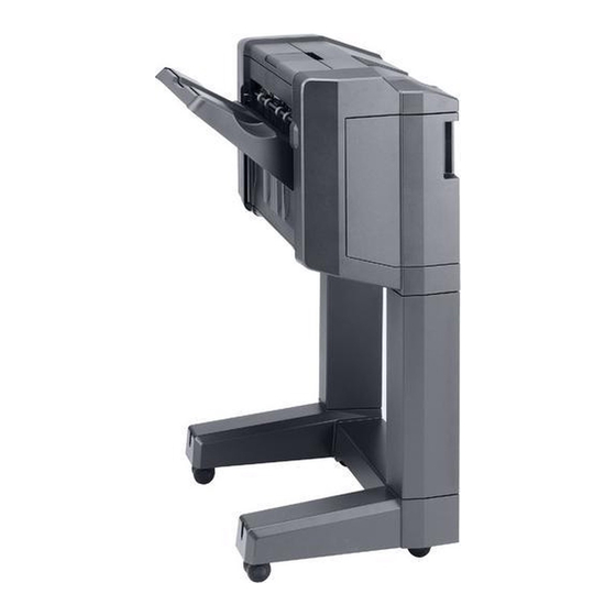
All manuals and user guides at all-guides.com 3NC/3NB/3NK 1-1-2 Parts names (1) Document Finisher Figure 1-1-1 1. DF Main tray(tray A) 2. DF tray extension 3. DF top cover 4. DF Sub tray(tray B) 5. DF Front cover 1-1-2... -
Page 15: Bridge Unit
All manuals and user guides at all-guides.com 3NC/3NB/3NK (2) Bridge unit Figure 1-1-2 1. Bridge eject cover 2. Bridge conveying unit 3. Bridge conveying cover 4. Bridge drive unit 5. Bridge entry unit 1-1-3... -
Page 16: Machine Cross Section
All manuals and user guides at all-guides.com 3NC/3NB/3NK 1-1-3 Machine cross section Paper path Figure 1-1-3 1. DF processing section 2. Eject tray section 3. Bridge unit section 4. Punch unit (Option) 1-1-4... -
Page 17: Installation Environment
All manuals and user guides at all-guides.com 3NC/3NB/3NK 1-2 Installation 1-2-1 Installation environment Installation location (Be based on the machine establishment place.) Avoid direct sunlight or bright lighting. Ensure that the photoconductor will not be exposed to direct sunlight or other strong light when removing paper jams. -
Page 18: Unpacking
All manuals and user guides at all-guides.com 3NC/3NB/3NK 1-2-2 Unpacking (1) Unpacking Document Finisher 18 19 20 21 Figure 1-2-1 1. Skid 7. Plastic sheet 13. Spacer C 19. M4 x 10 screw(black) 2. Bottom right pad 8. Outer case 14. - Page 19 All manuals and user guides at all-guides.com 3NC/3NB/3NK Bridge unit 18 19 20 21 22 12 11 Figure 1-2-2 1. Outer case 7. Spacer A 13. Lower connevtion 18. Edging 2. Bottom spacer 8. Spacer B cover 19. Wire stopper 9.
-
Page 20: Removing The Tapes And Pads
All manuals and user guides at all-guides.com 3NC/3NB/3NK (2) Removing the tapes and pads 1. Remove tape from the finisher try. Tape Figure 1-2-3 2. Remove tape from the document finisher. Tape Figure 1-2-4 1-2-4... - Page 21 All manuals and user guides at all-guides.com 3NC/3NB/3NK 3. Open the DF front cover. DF front cover Figure 1-2-5 4. Remove four tapes. Tape Tape Tape Tape Figure 1-2-6 1-2-5...
- Page 22 All manuals and user guides at all-guides.com 3NC/3NB/3NK 5. Remove tape from the DF rear cover. DF rear cover Tape Figure 1-2-7 6. Remove the lid rear cover and then remove tape . Tape Lid rear cover Figure 1-2-8 1-2-6...
- Page 23 All manuals and user guides at all-guides.com 3NC/3NB/3NK 7. Remove tape from the bridge entry unit. Tape Figure 1-2-9 8. Remove five tapes from bridge convey- ing unit. Tapes Tape Tapes Figure 1-2-10 1-2-7...
- Page 24 All manuals and user guides at all-guides.com 3NC/3NB/3NK 9. Remove two tapes from the bridge eject unit. Tape Tape Figure 1-2-11 10. Remove three tapes and two pads. Tape Tape Tape Figure 1-2-12 1-2-8...
- Page 25 All manuals and user guides at all-guides.com 3NC/3NB/3NK 11. Remove tape from the bridge drive unit. Tape Figure 1-2-13 1-2-9...
- Page 26 All manuals and user guides at all-guides.com 3NC/3NB/3NK This page is intentionally left blank. 1-2-10...
-
Page 27: Maintenance Mode
All manuals and user guides at all-guides.com 3NC/3NB/3NK 1-3 Maintenance Mode 1-3-1 Maintenance mode The machine is equipped with a maintenance function which can be used to maintain and service the machine. (1) Executing a maintenance item Start Enter “10871087” using Maintenance mode is entered. -
Page 28: Maintenance Modes Item List
All manuals and user guides at all-guides.com 3NC/3NB/3NK (2) Maintenance modes item list Item Section Content of maintenance item Initial setting General U019 Displaying the ROM version Others U905 Checking counts by optional devices 1-3-2... -
Page 29: Contents Of The Maintenance Mode Items
All manuals and user guides at all-guides.com 3NC/3NB/3NK Contents of the maintenance mode items Item No. Description U019 Displaying the ROM version Description Displays the part number of the ROM fitted to each PWB. Purpose To check the part number or to decide, if the newest version of ROM is installed. Method 1. - Page 30 All manuals and user guides at all-guides.com 3NC/3NB/3NK Item No. Description U019 Display Description Side PF Boot SMT paper feeder /Side feeder booting Side paper feeder / Side large capacity feeder ROM PF2 Boot Side paper feeder / Side large capacity feeder booting 1000-sheet finisher / 4000-sheet finisher ROM DF Boot 1000-sheet finisher / 4000-sheet finisher booting...
- Page 31 All manuals and user guides at all-guides.com 3NC/3NB/3NK Item No. Description U905 Checking counts by optional devices Description Displays the counts of DP, 1000-sheet or 4000-sheet finisher. Purpose To check the use of DP, 1000-sheet or 4000-sheet finisher. Method 1. Press the start key. 2.
- Page 32 All manuals and user guides at all-guides.com 3NC/3NB/3NK This page is intentionally left blank. 1-3-6...
-
Page 33: Paper Misfeed Detection
All manuals and user guides at all-guides.com 3NC/3NB/3NK 1-4 Troubleshooting 1-4-1 Paper misfeed detection (1) Paper misfeed indication When a paper misfeed occurs, the machine immediately stops printing and displays the paper misfeed mes- sage on the operation panel. To remove paper misfed in the machine, pull out the cassette, open the paper conveying unit or paper conveying cover. -
Page 34: Paper Misfeed Detection Condition
All manuals and user guides at all-guides.com 3NC/3NB/3NK (2) Paper misfeed detection condition DFPES BRES DFEPS DFMES BRCS1 BRCS2 Figure 1-4-2 Paper jam location 1-4-2... - Page 35 All manuals and user guides at all-guides.com 3NC/3NB/3NK Code Contents Conditions location* 0114 Bridge cover open The bridge cover is opened during printing. 0115 Bridge eject cover open The bridge eject cover is opened during printing. 4901 Bridge conveying sensor 1 Bridge conveying sensor 1 (BRCS1) does not non arrival jam turn on during paper feed from cassette 1.
- Page 36 All manuals and user guides at all-guides.com 3NC/3NB/3NK Code Contents Conditions location* 4911 Bridge conveying sensor 1 Bridge conveying sensor 1 (BRCS1) does not stay jam turn off during paper feed from cassette 1. 4912 Bridge conveying sensor 1 (BRCS1) does not turn off during paper feed from cassette 2.
- Page 37 All manuals and user guides at all-guides.com 3NC/3NB/3NK Code Contents Conditions location* 5008 Bridge conveying sensor 2 Bridge conveying sensor 2 (BRCS2) does not non arrival jam turn on during paper feed from duplex section. 5009 Bridge conveying sensor 2 (BRCS2) does not turn on during paper feed from MP tray.
- Page 38 All manuals and user guides at all-guides.com 3NC/3NB/3NK Code Contents Conditions location* 5107 Bridge eject sensor non Bridge eject sensor (BRES) does not turn on dur- arrival jam ing paper feed from cassette 7 (side paper feeder). 5108 Bridge eject sensor (BRES) does not turn on dur- ing paper feed from duplex section.
- Page 39 All manuals and user guides at all-guides.com 3NC/3NB/3NK Code Contents Conditions location* 6100 DF paper entry sensor non DF paper entry sensor (DFPES) is not turned on arrival jam even if a specified time has elapsed after the machine eject signal was received (4000-sheet finisher).
- Page 40 All manuals and user guides at all-guides.com 3NC/3NB/3NK Code Contents Conditions location* 6320 DF middle eject sensor DF middle eject sensor (DFMES) does turned on remaining jam when the power is turned on or cover close (4000-sheet finisher). 6321 DF middle eject sensor (DFMES) does turned on when the power is turned on or cover close (1000-sheet finisher).
- Page 41 All manuals and user guides at all-guides.com 3NC/3NB/3NK Code Contents Conditions location* 6910 DF side registration sensor 2 DF side registration sensor 2 (DFSRS2) is not stay jam turned off within specified time after driving the DF side registration motor 2 (DFSRM2) (4000- sheet finisher).
-
Page 42: Self-Diagnostic Function
All manuals and user guides at all-guides.com 3NC/3NB/3NK 1-4-2 Self-diagnostic function (1) Self-diagnostic function This machine is equipped with self-diagnostic function. When a problem is detected, the machine stops print- ing and display an error message on the operation panel. An error message consists of a message prompting a contact to service personnel and a four-digit error code indicating the type of the error. -
Page 43: Self Diagnostic Codes
All manuals and user guides at all-guides.com 3NC/3NB/3NK (2) Self diagnostic codes If the part causing the problem was not supplied, use the unit including the part for replacement. Check procedures/ Code Contents Causes corrective measures 8010 Punch motor error 1 Defective connec- Reinsert the connector. - Page 44 All manuals and user guides at all-guides.com 3NC/3NB/3NK Check procedures/ Code Contents Causes corrective measures 8030 Punch motor error 3 Defective connec- Reinsert the connector. Also check for conti- Home position does not turn tor cable or poor nuity within the connector cable. If none, from On to Off in 50 ms after contact in the con- replace the cable.
- Page 45 All manuals and user guides at all-guides.com 3NC/3NB/3NK Check procedures/ Code Contents Causes corrective measures 8100 DF eject release motor error Defective connec- Reinsert the connector. Also check for conti- When the DF eject release tor cable or poor nuity within the connector cable. If none, motor is driven, DF bundle contact in the con- replace the cable.
- Page 46 All manuals and user guides at all-guides.com 3NC/3NB/3NK Check procedures/ Code Contents Causes corrective measures 8130 DF shift release motor error Defective connec- Reinsert the connector. Also check for conti- When the DF shift release tor cable or poor nuity within the connector cable. If none, motor is driven, DF shift contact in the con- replace the cable.
- Page 47 All manuals and user guides at all-guides.com 3NC/3NB/3NK Check procedures/ Code Contents Causes corrective measures 8150 DF tray motor error 2 Defective connec- Reinsert the connector. Also check for conti- When the main tray has tor cable or poor nuity within the connector cable. If none, descended, DF tray sensor 1 contact in the con- replace the cable.
- Page 48 All manuals and user guides at all-guides.com 3NC/3NB/3NK Check procedures/ Code Contents Causes corrective measures 8170 DF side registration motor 1 Defective connec- Reinsert the connector. Also check for conti- error 1 tor cable or poor nuity within the connector cable. If none, When initial operation, DF contact in the con- replace the cable.
- Page 49 All manuals and user guides at all-guides.com 3NC/3NB/3NK Check procedures/ Code Contents Causes corrective measures 8190 DF side registration motor 2 Defective connec- Reinsert the connector. Also check for conti- error 1 tor cable or poor nuity within the connector cable. If none, When initial operation, DF contact in the con- replace the cable.
- Page 50 All manuals and user guides at all-guides.com 3NC/3NB/3NK Check procedures/ Code Contents Causes corrective measures 8210 DF slide motor error Defective connec- Reinsert the connector. Also check for conti- When initial operation, DF sta- tor cable or poor nuity within the connector cable. If none, ple sensor does not turn on contact in the con- replace the cable.
- Page 51 All manuals and user guides at all-guides.com 3NC/3NB/3NK Check procedures/ Code Contents Causes corrective measures 8410 Punch slide motor error 1 Defective connec- Reinsert the connector. Also check for conti- The punch slide sensor won’t tor cable or poor nuity within the connector cable. If none, turn On when home position contact in the con- replace the cable.
- Page 52 All manuals and user guides at all-guides.com 3NC/3NB/3NK Check procedures/ Code Contents Causes corrective measures 8800 Document finisher commu- Defective connec- Reinsert the connector. Also check for conti- nication error tor cable or poor nuity within the connector cable. If none, Communication with the docu- contact in the con- replace the cable.
-
Page 53: Electric Problems
All manuals and user guides at all-guides.com 3NC/3NB/3NK 1-4-3 Electric problems If the part causing the problem was not supplied, use the unit including the part for replacement. Troubleshooting to each failure must be in the order of the numbered symptoms. Problem Causes Check procedures/corrective measures... - Page 54 All manuals and user guides at all-guides.com 3NC/3NB/3NK Problem Causes Check procedures/corrective measures 1. Defective connector Reinsert the connector. Also check for continuity within the DF eject motor cable or poor con- connector cable. If none, replace the cable. does not operate. tact in the connector.
- Page 55 All manuals and user guides at all-guides.com 3NC/3NB/3NK Problem Causes Check procedures/corrective measures 1. Defective connector Reinsert the connector. Also check for continuity within the Bridge conveying cable or poor con- connector cable. If none, replace the cable. motor1,2 does not tact in the connector.
-
Page 56: Mechanical Problems
All manuals and user guides at all-guides.com 3NC/3NB/3NK 1-4-4 Mechanical problems If the part causing the problem was not supplied, use the unit including the part for replacement. Problem Causes/check procedures Corrective measures Paper outside specifications is used. Use only paper conforming to the speci- Paper jams. - Page 57 All manuals and user guides at all-guides.com 3NC/3NB/3NK Problem Causes/check procedures Corrective measures Check if the rollers, pulleys and gears Grease the bushes and gears. Abnormal noise is operate smoothly. heard. 1-4-25...
- Page 58 All manuals and user guides at all-guides.com 3NC/3NB/3NK This page is intentionally left blank. 1-4-26...
-
Page 59: Precautions For Assembly And Disassembly
All manuals and user guides at all-guides.com 3NC/3NB/3NK 1-5 Assembly and disassembly 1-5-1 Precautions for assembly and disassembly (1) Precautions Before starting disassembly, press the Power key on the operation panel to off. Make sure that the Power lamp is off before turning off the main power switch. And then unplug the power cable from the wall outlet. When handling PWBs (printed wiring boards), do not touch parts with bare hands. -
Page 60: Document Finisher Section
All manuals and user guides at all-guides.com 3NC/3NB/3NK 1-5-2 Document finisher section (1) Detaching and refitting the front cover and rear cover Procedure 1. Open the DF front cover. DF front cover 2. Remove three screws and then remove (Assemble) the DF front cover.(Assemble) DF front cover Screw... - Page 61 All manuals and user guides at all-guides.com 3NC/3NB/3NK 4. Remove two screws and then remove the DF rear cover. DF rear cover Screw Screw Figure 1-5-3 1-5-3...
-
Page 62: Detaching And Refitting The Pf Main Pwb
All manuals and user guides at all-guides.com 3NC/3NB/3NK (2) Detaching and refitting the PF main PWB Procedure DF main PWB 1. Remove the DF rear cover. 2. Remove all connectors from the DF main PWB. 3. Remove four screws. 4. Remove the DF main PWB. 5. -
Page 63: Detaching And Refitting The Staple Unit
All manuals and user guides at all-guides.com 3NC/3NB/3NK (3) Detaching and refitting the Staple unit Procedure 1. Open the DF front cover. DF front cover Figure 1-5-5 Staple cover 2. Insert a flat screwdriver under the lever of the staple cover. Lift the lever upwards to open. - Page 64 All manuals and user guides at all-guides.com 3NC/3NB/3NK 4. Raise the front of the staple unit and Hook pull the staple unit frontwards. 5. Check or replace the Staple unit and refit all the removed parts. Figure 1-5-7 1-5-6...
-
Page 65: Remarks On Finisher Pwb Replacement
All manuals and user guides at all-guides.com 3NC/3NB/3NK 1-6 Requirements on PWB Replacement 1-6-1 Remarks on finisher PWB replacement When replacing the finisher PWB, remove the EEPROM (U4) from the finisher PWB that has been removed and then reattach it to the new finisher PWB. DF main PWB DF main PWB Figure 1-6-1... - Page 66 All manuals and user guides at all-guides.com 3NC/3NB/3NK This page is intentionally left blank. 1-6-2...
-
Page 67: Bridge Unit Section
All manuals and user guides at all-guides.com 3NC/3NB/3NK 2-1 Mechanical Construction 2-1-1 Bridge unit section The bridge unit section consists of the parts shown in figure below and discharges paper conveyed from the machine to the document finisher or DF sub tray. Figure 2-1-1 Bridge unit section 1. - Page 68 All manuals and user guides at all-guides.com 3NC/3NB/3NK EPWB BRPWB YC20 YC20 BRIDGE2_B/,A/,B,A YC7-5,6,7,8 BRIDGE_SENS2 YC4-2 BRIDGE1_B/,A/,B,A YC7-1,2,3,4 BRIDGE_SENS1 YC6-2 BRSOL BRES BRCM BRCM BRCS2 BRCS1 Figure 2-1-2 Bridge unit section block diagram 2-1-2...
-
Page 69: Prosessing Section
All manuals and user guides at all-guides.com 3NC/3NB/3NK 2-1-2 Prosessing section The processing section consists of the parts shown in figure below and discharges paper conveyed from the bridge section to the eject tray. Also this section performs processing in the bundle discharge mode and the staple mode. - Page 70 All manuals and user guides at all-guides.com 3NC/3NB/3NK DFMPWB PAP ENT SIG YC19-2 MIDDLE MOT 2B,1B,2A,1A YC10-5,6,7,8 ADJUST SENS SIG YC20-6 PADDLE MOT 2B,1B,2A,1A YC11-1,2,3,4 DFPDM EJE RELS MOT DFADS 2B,1B,2A,1A YC10-13,14,15,16 DFERM EJE PAP SENS SIG YC20-26 DFMM DFEPS BUNDLE SENS SIG DFPES YC20-3...
-
Page 71: Bundle Discharge Operation
All manuals and user guides at all-guides.com 3NC/3NB/3NK (1) Bundle discharge operation Bundle discharge unit 1. Paper is fed to the processing section DF eject release motor by rotation of the middle roller and the middle eject roller. When the paper is conveyed into the processing section, the DF eject release motor is driven to raise the bundle discharge unit. -
Page 72: Eject Tray Section
All manuals and user guides at all-guides.com 3NC/3NB/3NK 2-1-3 Eject tray section The eject tray section consists of the parts shown in figure below and stocks paper discharged from the pro- cessing section. The upper limit position ,the middle position and the lower limit position of the eject tray are detected with the DF tray sensor 1,2,3(DFTS1,2,3) . - Page 73 All manuals and user guides at all-guides.com 3NC/3NB/3NK DFMPWB TRY MOT OUT1A,1B YC14-1,2 DFTM TRY HP SENS SIG YC20-9 DFTS1 TRY HALF SENS SIG YC20-12 DFTS2 TRY FULL SENS SIG DFTS3 YC20-15 Figure 2-1-7 Eject tray section block diagram 2-1-7...
-
Page 74: Punch Unit(Option)
All manuals and user guides at all-guides.com 3NC/3NB/3NK 2-1-4 Punch unit(Option) Figure 2-1-8 Punch unit 1. Punch cam 2. Punch cutter 3. Punch waste box 4. Punch home position sensor(PUHPS) 5. Punch plus sensor(PUPS) 2-1-8... - Page 75 All manuals and user guides at all-guides.com 3NC/3NB/3NK PUNPWB PHMOT_N,P YC1-1,3 PHMOT_HP 24V2 PUHPS YC8-6 YC2-2 PHMOT_PLS PUPS YC8-3 PHTNK_FUL YC5-10 PUTFS PHSOL_PUL,RET PUSOL YC5-2,3 PHPES_DET YC7-1 PUPES2 PHADJ_HP YC6-3 PUSLS PHLED_A,B,C,D YC5-2,3,4,5 PUPES1 PHADJ_MOT 2B,1B 2A,1A PUSLM YC3-1,2,3,4 DFMPWB Figure 2-1-9 Punch unit block diagram 2-1-9...
- Page 76 All manuals and user guides at all-guides.com 3NC/3NB/3NK This page is intentionally left blank. 2-1-10...
-
Page 77: Electrical Parts Layout
All manuals and user guides at all-guides.com 3NC/3NB/3NK 2-2 Electrical Parts Layout 2-2-1 Electrical parts layout (1) PWBs Machine front Machine inside Machine rear Figure 2-2-1 PWBs 1. DF main PWB (DFMPWB)....Controls electrical components. 2-2-1... -
Page 78: Switches And Sensors
All manuals and user guides at all-guides.com 3NC/3NB/3NK (2) Switches and sensors 13,14 Machine front Machine inside Machine rear Figure 2-2-2 Switches and sensors 1. DF paper entrance sensor (DFPES) ..Detects a paper misfeed in the entrance section. 2. DF middle sensor (DFMS) ....Detects a paper misfeed in the conveying section. 3. -
Page 79: Motors
All manuals and user guides at all-guides.com 3NC/3NB/3NK (3) Motors Machine front Machine inside Machine rear Figure 2-2-3 Motors 1. DF middle motor (DFPEM) ....Drives the middle roller. 2. DF middle eject motor (DFMM)..... Drives the middle eject roller. 3. -
Page 80: Bridge Section
All manuals and user guides at all-guides.com 3NC/3NB/3NK (4) Bridge section Machine front Machine inside Machine rear Figure 2-2-4 Bridge section 1. Bridge PWB (BRPWB)......Controls the paper conveying section. 2. Bridge conveying sensor1 (BRCS1) ..Detects a paper misfeed in the bridge section. 3. -
Page 81: Punch Unit(Option)
All manuals and user guides at all-guides.com 3NC/3NB/3NK (5) Punch unit(Option) Figure 2-2-5 Bridge section 1. Punch PWB (PUNPWB) ....... Controls electric components of punch unit. 2. Punch home position sensor (PUHPS) ..........Detects home position of the punch cam. 3. - Page 82 All manuals and user guides at all-guides.com 3NC/3NB/3NK This page is intentionally left blank. 2-2-6...
-
Page 83: Df Main Pwb
All manuals and user guides at all-guides.com 3NC/3NB/3NK 2-3 Operation of the PWBs 2-3-1 DF main PWB YC12 YC14 YC10 YC17 YC13 YC20 YC18 Figure 2-3-1 DF main PWB silk-screen diagram Connector Signal Voltage Description Ground Connected to Ground machine 24V1 24 V DC 24 V DC power input from Machine... - Page 84 All manuals and user guides at all-guides.com 3NC/3NB/3NK Connector Signal Voltage Description Ground Ground Connected to machine ENG RDY 0/3.3 V DC Ready signal to the machine ENG SEL 0/3.3 V DC Select signal from the machine ENG CLK 0/3.3 V DC(pulse) Serial communication clock signal ENG DI 0/3.3 V DC(pulse) Serial communication data signal input...
- Page 85 All manuals and user guides at all-guides.com 3NC/3NB/3NK Connector Signal Voltage Description ENTRY MOT 1A 0/24 V DC(pulse) DFPEM drive control signal EJE RELS MOT 2B 0/24 V DC(pulse) DFERM drive control signal EJE RELS MOT 1B 0/24 V DC(pulse) DFERM drive control signal EJE RELS MOT 2A 0/24 V DC(pulse)
- Page 86 All manuals and user guides at all-guides.com 3NC/3NB/3NK Connector Signal Voltage Description STP_MOT OUT2 0/24 V DC(pulse) DFSTM drive control signal YC12 STP_MOT OUT2 0/24 V DC(pulse) DFSTM drive control signal Connected to the staple unit STP_MOT OUT2 0/24 V DC(pulse) DFSTM drive control signal STP_MOT OUT2 0/24 V DC(pulse)
- Page 87 All manuals and user guides at all-guides.com 3NC/3NB/3NK Connector Signal Voltage Description BUNDLE SENS A 3.3V DC 3.3 V DC power output to DFBDS YC20 Connected to Ground the DF band- BUNDLE SENS 0/3.3V DC DFBDS: On/Off dle discharge unit sensor, DF adjustment ADJUST SENS A 3.3V DC...
-
Page 88: Bridge Pwb
All manuals and user guides at all-guides.com 3NC/3NB/3NK 2-3-2 Bridge PWB Figure 2-3-2 Bridge PWB silk-screen diagram Connector Signal Voltage Description +24V 24V DC 24 V DC power input from machine +24V 24V DC 24 V DC power input from machine Connected to the machine Ground... - Page 89 All manuals and user guides at all-guides.com 3NC/3NB/3NK Connector Signal Voltage Description Ground Connected to BRIDGE_SENS 2 0/5V DC BRCM2: On/Off the bridge 5V DC 5 V DC power output to BRCS2 conveying sensor 2 Ground Connected to BRIDGE_SENS 1 0/5V DC BRCS1: On/Off the bridge...
-
Page 90: Punch Unit Pwb
All manuals and user guides at all-guides.com 3NC/3NB/3NK 2-3-3 Punch unit PWB YC10 YC11 Figure 2-3-3 Punch unit PWB silk-screen diagram Connector Signal Voltage Description PH_SDI 0/3.3V DC(pulse) Serial communication data signal input PH_SDO 0/3.3V DC(pulse) Serial communication data signal output Connected to the machine PH_CLK... - Page 91 All manuals and user guides at all-guides.com 3NC/3NB/3NK Connector Signal Voltage Description PHADJ_MOT 0/24V DC(pulse) PUSLM drive control signal PHADJ_MOT 0/24V DC(pulse) PUSLM drive control signal Connected to the punch slide motor PHADJ_MOT 0/24V DC(pulse) PUSLM drive control signal PHADJ_MOT 0/24V DC(pulse) PUSLM drive control signal PHMOT_N...
- Page 92 All manuals and user guides at all-guides.com 3NC/3NB/3NK Connector Signal Voltage Description PHTNK_SET 0/3.3V DC PUTSSW: On/Off Connected to Ground the punch tank set switch 2-3-10...
-
Page 93: Appendixes 2-4-1
All manuals and user guides at all-guides.com 3NC/3NB/3NK 2-4 Appendixes 2-4-1 Appendixes (1) Wiring diagram YC10 YC19 EJECT MOT 2B DFPES EJECT MOT 1B DFEM PAP ENT SIG EJECT MOT 2A 3.3V EJECT MOT 1A MID EJE SENS A DFMS MIDDLE MOT 2B MIDDLE MOT 1B MID EJE SENS SIG... - Page 94 All manuals and user guides at all-guides.com 3NC/3NB/3NK BRES Vout Relay YC20 BRECSW EXIT _ SENS EXIT _ COV _ OPEN EXIT _ SOL _ RET BRSOL EXIT _ SOL _ REM Relay +24V1 DECAL DIR DECAL _ DIR BRCS2 BRIDGE _ SENS2 DECAL _ PD Vout...
- Page 95 All manuals and user guides at all-guides.com 3NC/3NB/3NK PGND PHMOT_ N PHMOT_ N 24V2 24V2 PHMOT_ P PHMOT_ P PU_ DO PH_SDI PHADJ_ MOT 1A PHADJ_ MOT_ A PU_ DI PH_ SDO PHADJ_ MOT 2A PHADJ_ MOT_ B PUSLM PU_ CLK PH_ CLK PHADJ_ MOT 1B PHADJ_ MOT_ An...
- Page 96 All manuals and user guides at all-guides.com 2011...
- Page 97 All manuals and user guides at all-guides.com 2011...
Need help?
Do you have a question about the AK-730 and is the answer not in the manual?
Questions and answers