
Related Manuals for Nilfisk-Advance CS7010


Summary of Contents for Nilfisk-Advance CS7010
- Page 1 6/11 revised 8/2013 REV A FORM NO. 56041980 Models: 56509003(LPG), 56509004(Diesel), 56509005(Battery) 56511002(Petrol) Instructions for Use Original Instructions CS7000 INSTRUCTIONS FOR USE...
-
Page 2: Table Of Contents
A-2 / ENGLISH TABLE OF CONTENTS Page Introduction ...................A-2 Parts and Service ................A-3 Nameplate ..................A-3 Delivery ...................A-3 Cautions and Warnings ............A-4 – A-5 General Information ............... A-6 – A-7 Know Your Machine / Control Panel ........A-8 – A-12 Preparing the Machine for Use Pre-Operational Checklist ............. -
Page 3: Parts And Service
ENGLISH / A-3 PARTS AND SERVICE Repairs, when required, should be performed by your Authorized Nilf sk Service Center, who employs factory trained service personnel, and maintains an inventory of Nilf sk original replacement parts and accessories. Call the Nilf sk Authorized Service named below for repairs or service. Please specify the Model and Serial Number when discussing your machine. -
Page 4: Cautions And Warnings
A-4 / ENGLISH CAUTIONS AND WARNINGS Nilf sk uses the symbols below to signal potentially dangerous conditions. Always read this information carefully and take the necessary steps to protect personnel and property. DANGER! Is used to warn of immediate hazards that will cause severe personal injury or death. WARNING! Is used to call attention to a situation that could cause severe personal injury. - Page 5 ENGLISH / A-5 CAUTION! This machine is not approved for use on public paths or roads. • This machine is not suitable for picking up hazardous dust. • Use care when using scarif er discs and grinding stones. Nilf sk will not be held responsible for any damage to f oor •...
- Page 6 A-6 / ENGLISH HOPPER SAFETY BAR WARNING! Make sure the Hopper Safety Bar (23) is engaged whenever attempting to do any maintenance work under or near the raised hopper. The Hopper Safety Bar (23) holds the hopper in the raised position to allow work to be performed under the hopper. See Figure 1. NEVER rely on the machine’s hydraulic components to safely support the hopper.
- Page 7 ENGLISH / A-7 JACKING THE MACHINE CAUTION! Never work under a machine without safety stands or blocks to support the machine. When jacking the machine, do so at designated locations (Do Not jack on the hopper) - see Jack Point / Tie Down Point locations (33). •...
-
Page 8: Know Your Machine / Control Panel
A-8 / ENGLISH KNOW YOUR MACHINE As you read this manual, you will occasionally run across a bold number or letter in parentheses - example: (2). These numbers refer to an item shown on these pages unless otherwise noted. Refer back to these pages whenever necessary to pinpoint the location of an item mentioned in the text. - Page 9 ENGLISH / A-9 KNOW YOUR MACHINE (CONTINUED) 38 Brake Pedal/Parking Brake 24 Recovery Tank Lid Latch 25 Recovery Tank Tip-Out Grip 39 Right Scrub Skirt Assy 40 Edge Guard Retainer Knob 26 Circuit Breaker Panel (see troubleshooting) 27 Control Panel 41 Solution Filter 28 Radiator Cap 42 Solution Shut-Off Valve...
- Page 10 A-10 / ENGLISH CONTROL PANEL Key Switch Solution Flow Increase Switch Emergency Stop Solution Switch LCD Display Solution Flow Decrease Switch Left Turn Indicator W Vacuum/Wand Switch (see IS56090054) Left Turn Signal Detergent Switch Hazard Flasher One-Touch™ Sweep Switch Right Turn Signal Broom Height Raise Switch Right Turn Indicator AA Broom Select Switch...
- Page 11 ENGLISH / A-11 CONTROL PANEL (CONTINUED) Main Display Screen Battery Model LCD Display Main Display Screen LPG Model C1 Detergent Indicator (if so equipped) Main Display Screen Diesel Model C2 Solution Tank Level Broom Adjustment Screen C3 Sweep/Scrub Time (Battery models) C4 Engine Run Time (LPG &...
- Page 12 A-12 / ENGLISH CONTROL PANEL (CONTINUED) IF ANY OF THE WARNING / ATTENTION ICONS MARKED (X) BELOW ARE DISPLAYED PLEASE CONTACT YOUR NILFISK AUTHORIZED SERVICE CENTER. LCD Display C16 Glow Plug Caution Icon (Diesel models) C11 Non-Critical Fault C17 Critical Fault C12 Battery Low Indicator C18 Low Engine Starting Battery Warning Icon (LPG &...
-
Page 13: Pre-Operational Checklist
ENGLISH / A-13 PRE-OPERATIONAL CHECKLIST Before Each Use: Inspect the machine for damage, oil or coolant leaks. Squeeze the rubber dust cup on the Engine Air Filter (48) to release built-up dust. Check the Air Filter Service Indicator (29). Check the engine coolant level (22). Check the engine oil level (50). -
Page 14: Engine Oil
A-14 / ENGLISH ENGINE OIL – GASOLINE / PETROL, LP Check the engine oil level when the machine is parked on a level surface and the engine is cool. Change the engine oil after the f rst 50 hours of operation and every 200 hours after that. -
Page 15: Engine Air Filter
ENGLISH / A-15 PRE-OPERATIONAL CHECKLIST ENGINE AIR FILTER Check the Air Filter Service Indicator (29) before each use of the machine. Do not service the air f lter unless the red f ag is visible in the service indicator. CAUTION! When servicing the engine air f lter elements, use extreme care to prevent loose dust from entering the engine. -
Page 16: Battery Installation
A-16 / ENGLISH BATTERY INSTALLATION See Figure 3. The battery required for this machine is sold separately. The maximum battery weight for this machine is 1,875 lbs (850 kg); the minimum battery weight is 1,400 lbs (635kg). For proper battery installation, please consult your Nilf sk Industrial Dealer. DO NOT attempt to install the battery with an overhead hoist or forklift;... -
Page 17: Main Broom
ENGLISH / A-17 MAIN BROOM Several different main brooms are available for this machine. Contact your Nilf sk dealer if you need help selecting the best broom for the surface and litter that you will be sweeping. Note: Reference broom maintenance for installation steps. SCRUB BRUSHES Make sure the Key Switch (B) is OFF (O). -
Page 18: Filling The Solution Tank & Dustguard™ Tank
A-18 / ENGLISH FILLING THE SOLUTION TANK See Figure 6. Fill the solution tank with a maximum of 75 gallons (284 Liters) of cleaning solution. Do not f ll the solution tank above 7.5 cm (3 inches) from the bottom of the Solution Fill (4). The solution should be a mixture of water and the proper cleaning chemical for the job. Always follow the dilution instructions on the chemical container label. -
Page 19: Operating The Machine
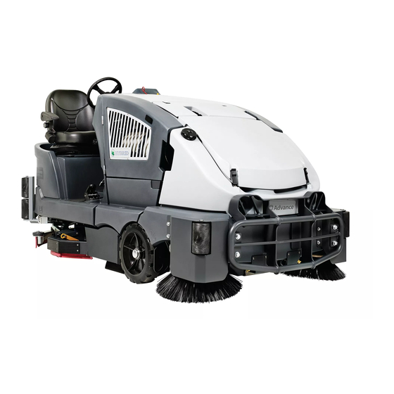
ENGLISH / A-19 OPERATING THE MACHINE The CS7000 is a rider-type automatic f oor sweeping and scrubbing machine. It is designed to sweep up debris, lay down cleaning solution, scrub the f oor, and vacuum dry all in one pass. The sweeping and scrubbing operations can also be performed separately. The controls were designed with one touch operation in mind. -
Page 20: Detergent System (Ecoflex™ Only)
A-20 / ENGLISH DETERGENT SYSTEM PREPARATION AND USE (ECOFLEX MODELS ONLY) The Detergent Cartridges (47) are located below the Operator’s Seat (2). Fill the detergent cartridge with a maximum of 2.2 gallons (8.32 Liters) of detergent. SERVICE NOTE: Remove the detergent cartridge from the detergent box prior to f lling to avoid spilling detergent on the machine. It is recommended that a separate cartridge be used for each detergent you plan to use. - Page 21 ENGLISH / A-21 DETERGENT SYSTEM PREPARATION AND USE (ECOFLEX MODELS ONLY) FIGURE 7 FORM NO. 56041980 - CS7000 - A-21...
-
Page 22: Sweeping
A-22 / ENGLISH SWEEPING WARNING! Be sure you understand the operator controls and their functions. While on ramps or inclines, avoid sudden stops when loaded. Avoid abrupt sharp turns. Use low speed down hills. Follow the instructions in preparing the machine for use section of this manual. Start the engine following the instructions in the appropriate “Starting the …... - Page 23 ENGLISH / A-23 FORM NO. 56041980 - CS7000 - A-23...
-
Page 24: Scrubbing
A-24 / ENGLISH SCRUBBING WARNING! Be sure you understand the operator controls and their functions. While on ramps or inclines, avoid sudden stops when loaded. Avoid abrupt sharp turns. Use low speed down hills. Follow the instructions in preparing the machine for use section of this manual. Start the engine following the instructions in the appropriate “Starting the …... - Page 25 ENGLISH / A-25 FORM NO. 56041980 - CS7000 - A-25...
-
Page 26: Shutting Down The Diesel Engine
A-26 / ENGLISH AFTER USE Raise the scrub brushes and the brooms. Shake the dust control f lter and empty the hopper. 3 Drain and f ush the recovery tank. Check that the drain hose cap is sealed. Flush the vacuum hose and squeegee by opening the recovery tank lid and running water down the pickup tube on the rear of the tank. SERVICE NOTE: The recovery tank can be tipped out to the side for cleaning after emptying. -
Page 27: Maintenance Schedule
ENGLISH / A-27 MAINTENANCE SCHEDULE Keep the machine in top condition by following the maintenance schedule closely. Maintenance intervals given are for average operating conditions. Machines used in severe environments may require service more often. MAINTENANCE ITEM PERFORM DAILY PERFORM WEEKLY Perform the “After Use”... - Page 28 A-28 / ENGLISH LUBRICATING THE MACHINE – FIGURE 11 Once a month, pump a small amount of grease into each grease f tting on the machine until grease seeps out around the bearings. Grease fi tting locations (or apply grease to) (DE): •...
-
Page 29: Charging The Battery (Battery Models
ENGLISH / A-29 CHARGING THE BATTERY (BATTERY MODELS) Charge the battery each time the machine is used, or whenever the Battery Low Indicator (C12) is displayed. To Charge the Battery... Unlatch the Battery Compartment Latch (20) and open the door to provide proper ventilation. Disconnect the battery from the machine (AB) and connect the charger plug to the battery plug. -
Page 30: Charging The Battery Pack (Hybrid Models
A-30 / ENGLISH CHARGING THE BATTERY PACK (HYBRID MODELS) The engine runs a generator which is the main source of electrical power. The battery pack (32) is used as a back-up. If the engine is not running, the machine can operate for a limited time using only the battery pack. Charge the battery pack whenever the Battery Low Indicator (C12) is displayed (signifying a low-voltage cutout state). - Page 31 ENGLISH / A-31 MAIN BROOM MAINTENANCE Since the Main Broom Motor always turns in the same direction, the bristles on the broom eventually become curved, reducing sweeping performance. Sweeping performance can be improved by removing the broom and turning it around (end-for-end). This procedure, known as “rotating”...
-
Page 32: Main Broom Maintenance
A-32 / ENGLISH MAIN BROOM MAINTENANCE To Adjust the Main Broom Height... Drive the machine to an area with a level f oor and set the parking brake. See Figure 13. Press the One-Touch™ Sweep Switch (Y) to lower the main broom. DO NOT move the machine. Lightly press the Drive Pedal (37) to start the main broom and let it run in place for 1 minute. -
Page 33: Side Broom Maintenance
ENGLISH / A-33 SIDE BROOM MAINTENANCE The side brooms move dirt and debris away from walls or curbs and into the path of the main broom. Adjust the side brooms so that the bristles are contacting the f oor from the (FG) to (FH) area shown in Figure 14 when the broom is down and running. To adjust the Side Broom... -
Page 34: Squeegee Maintenance
A-34 / ENGLISH SQUEEGEE MAINTENANCE If the squeegee leaves narrow streaks or water, the blades may be dirty or damaged. Remove the squeegee, rinse it under warm water and inspect the blades. Reverse or replace the blades if they are cut, torn, wavy or worn. To Reverse or Replace the Rear Squeegee FIGURE 15 Wiping Blade... -
Page 35: Hopper Dust Control Filter
ENGLISH / A-35 HOPPER DUST CONTROL FILTER The hopper dust control f lter must be cleaned regularly to maintain the eff ciency of the vacuum system. Follow the recommended f lter service intervals for the longest f lter life. CAUTION! Use only the approved Nilf sk high capacity dust control f lter in this machine. -
Page 36: Side Skirt Maintenance
A-36 / ENGLISH SIDE SKIRT MAINTENANCE CAUTION! Turn the key switch off (O) and remove the key, before changing the brushes, and before opening any access panels. The side skirt’s function is to channel the waste water to the squeegee, helping contain the water within the machines cleaning path. During normal use the blades will wear in time. -
Page 37: Troubleshooting
ENGLISH / A-37 TROUBLESHOOTING If the possible causes listed below are not the source of trouble, it is a symptom of something more serious. Contact your Nilf sk Service Center immediately for service. TRIPPING THE CIRCUIT BREAKERS The circuit breakers are located on the Circuit Breaker Panel in the operator’s compartment; they protect electrical circuits and motors from damage due to overload conditions. - Page 38 A-38 / ENGLISH GENERAL MACHINE TROUBLESHOOTING Before you start troubleshooting , check to make sure: • the emergency stop switch (B) on the operator control panel is disengaged (rotate clockwise). • the seat switch is closed. • the battery stop plate (AC) is in place (battery models). •...
- Page 39 ENGLISH / A-39 Problem Possible Cause Remedy Parking brake set Release parking brake No FWD/REV wheel drive Emergency Stop activated Rotate Emergency Stop knob clockwise to reset. Tripped circuit breakers Reset any tripped circuit breakers Plugged squeegee hose Clear debris Vacuum shuts off and display Vacuuming large amounts of water Slow down or disable auto shut-off feature...
-
Page 40: Technical Specif Cations
A-40 / ENGLISH TECHNICAL SPECIFICATIONS (as installed and tested on the unit) CS7000 CS7000 CS7000 Model Hybrid (Petrol) Hybrid (LPG) Hybrid (Diesel) Model No. 56511002 56509003 56509004 Protection Grade IPX4 IPX4 IPX4 Sound Pressure Level (ISO 11201) 82dB LpA, 3dB u(L 82dB LpA, 3dB u(L 81dB LpA, 3dB u(L Sound Power Level (ISO 3744) -
Page 41: Material Composition And Recyclability
ENGLISH / A-41 Material Composition and Recyclability % of machine weight % of machine weight % of machine weight Type % recyclable Gasoline/Petrol / LP Diesel Battery Aluminum 0.5% 0.5% 0.3% Electrical / motors / engines - misc 29.3% 50.1% Ferrous metals 53.8% 35.2%... - Page 43 EN 61000-6-2, EN 55012 EC Machinery Directive 06/42/EC EN 12100-1, EN 12100-2, EN 294, EN 349 2.16.2011 Don Legatt, Engineering Director Nilfisk-Advance, Inc. Nilfisk-Advance A/S 14600 21st Avenue North Sognevej 25 Plymouth, MN 55447 USA DK-2605 Brøndby, Denmark ©Nilfisk-Advance Incorporated, 2011 .pas...
Need help?
Do you have a question about the CS7010 and is the answer not in the manual?
Questions and answers