Table of Contents
Advertisement
Quick Links
Advertisement
Table of Contents

Related Manuals for Dahua DH-SD1A


Summary of Contents for Dahua DH-SD1A
- Page 1 Network Speed Dome Installation Manual Version 1.0.0...
-
Page 2: Table Of Contents
Table of Contents INSTALLATION PREPARATION .................... 1 Basic Requirement ......................1 Installation Check ........................ 1 Cable Preparation ........................ 1 1.3.1 The Min Specification Requirements of Cable ..............1 1.3.2 Cable Selection ....................... 1 SPEED DOME INSTALLATION ....................2 Check Accessories ......................2 Open Device ........................ - Page 3 Welcome Thank you for purchasing our speed dome! Please read the following safeguards and warnings carefully before you install or use the product!
- Page 4 Important Safeguards and Warnings Safety Measures 1. Qualified Engineer Needed The installation engineer or maintenance engineer shall have corresponding CCTV system installation certificate or maintenance qualification certificate. The installation engineer or maintenance engineer shall have qualification certificate for work at height.
- Page 5 All the examination and repair work should be done by the qualified service engineers. We are not liable for any problems caused by unauthorized modifications or attempted repair. This device complies with Part 15 of the FCC Rules. Operation is subject to the following two conditions: (1) This device may not cause harmful interference, and (2) This device must accept any interference received, including interference that may cause...
- Page 6 This series product shall be away from the strong electromagnetism radiant, please keep it away from wireless power, TV transmitter, transformer and etc. 7. Daily Maintenance Please use the soft cloth to clean dust on the shell, or you can use soft cloth with cleaning liquid to clean the shell and then use soft cloth to make it dry.
-
Page 7: Installation Preparation
1 Installation Preparation 1.1 Basic Requirement All installation and operation here should conform to your local electrical safety codes. Before installation, please open the package and check all the components are included. Please make sure the speed dome installation environment and installation mode can meet your requirement. -
Page 8: Speed Dome Installation
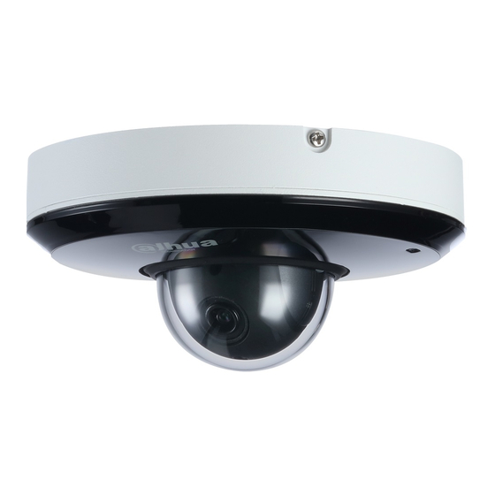
2 Speed Dome Installation 2.1 Check Accessories Before installation, please check the accessories one by one according to the packing list. Please make sure all the components listed are includes. 2.2 Open Device Please open the box and then take out the device, which is shown in Figure 2-1. Figure 2-1 2.3 Micro SD Card Slot and Reset Button Turn over the device and you can see there is a cover located on the bottom of the speed dome,... -
Page 9: Use Reset Button
Figure 2-3 2.3.1 Use Reset Button Reset button is used to reset the network system. Open the device cover, long press the reset button for over 10 seconds to reset the device, and then all the settings will be restored back to factory default. 2.3.2 Install Micro SD Card Micro SD card is used for data storage, the installation steps are shown as follows: Step 1... -
Page 10: Ceiling Mount
3 Ceiling Mount 3.1 Installation Component It needs to use installation position map when the speed dome adopts ceiling mount, which is shown in Figure 3-1. Figure 3-1 3.2 Device Installation 3.2.1 Installation Conditions Ceiling-mounted speed dome can be installed on the hard ceiling structure both indoors and outdoors, the ceiling needs to meet the following installation conditions: ... - Page 11 Figure 3-2 Step 2 Knock the expansion bolts into the mounting holes and use screws to fix the changeover plate on the ceiling, which is shown in Figure 3-3. Figure 3-3 Step 3 Place the speed dome pedestal closely to the changeover plate after pulling the cable through the hole, rotate it according to the arrow shown on the device edge and hang the speed dome on the changeover plate, which is shown in Figure 3-4.
- Page 12 Figure 3-4 Step 4 Insert the screws into the holes on the side of changeover plate to fix the speed dome together with the changeover plate, which is shown in Figure 3-5. Figure 3-5 Installation is completed, which is shown in Figure 3-6.
- Page 13 Figure 3-6...
-
Page 14: Wall Mount
4 Wall Mount 4.1 Installation Component As for wall mount, it needs to use wall-mounted bracket and ceiling bracket, which is shown in Figure 4-1 and Figure 4-2 respectively. Figure 4-1 Figure 4-2 4.2 Device Installation 4.2.1 Installation Conditions Wall-mounted speed dome can be installed on the hard wall structure both indoors and outdoors, the wall needs to meet the following installation conditions: ... -
Page 15: Installation Steps
The wall shall sustain at least 8X weight of the speed dome, bracket and other accessories. 4.3 Installation Steps Step 1 Pull the device cable through the ceiling changeover plate, which is shown in Figure 4-3. Figure 4-3 Step 2 Place the device cable closely into the wiring channel and use screws to install changeover plate of speed dome on the ceiling changeover plate, which is shown in Figure 4-4. - Page 16 Figure 4-4 Step 3 Rotate the speed dome clockwise after the device pedestal is closely clung to the changeover plate, and then hang the speed dome on the changeover plate, which is shown in Figure 4-5.
- Page 17 Figure 4-5 Step 4 Insert the screw into the holes on the side of changeover plate, and then fix the speed dome together with the changeover plate, which is shown in Figure 4-6.
- Page 18 Figure 4-6 Step 5 Pull the device cable and ceiling changeover plate flange through the wall-mounted bracket, twist the screws into the wall-mounted bracket, and then fix the changeover plate and speed dome on the wall-mounted bracket, which is shown in Figure 4-7. Note Make sure the wiring channel is located in the range which needs no monitoring due to the optics reason;...
- Page 19 Figure 4-7 Step 6 Fix the bracket on the wall after connecting the device cable to the wall cable, fix the bracket on the wall and speed dome installation is completed, which is shown in Figure 4-8. Figure 4-8...
-
Page 20: Appendix Ⅰ Lightning Proof And Surge Protection (Outdoors)
5 APPENDIX Ⅰ LIGHTNING PROOF AND SURGE PROTECTION (Outdoors) This series speed dome adopts TVS lighting protection technology. It can effectively prevent damages from various pulse signals below 6000W, such as sudden lighting and surge. While maintaining your local electrical safety code, you still need to take necessary precaution measures when installing the speed dome in the outdoor environment. - Page 21 The yellow and green GND wire or GND screw of the speed dome should be reliably connected by several strands of copper wire with no less than 25mm²and indoor equipotential GND terminal. Please refer to Figure 5-2 for lightningproof installation mode. Figure 5-2...
-
Page 22: Transmission Distance
6 APPENDIX Ⅱ THE RELATIONSHIP BETWEEN DC 12V CABLE DIAMETER AND TRANSMISSION DISTANCE It is the recommended max transmission distance when the cable diameter is fixed and the DC 12V power consumption is below 10%. For the DC power supply devices, the max permission voltage power consumption is 10%. The cable listed in the table below is copper wire (the resistivity of copper is Feet(m)... - Page 23 Feet(m) 0.8000 1.000 1.250 2.000 (11.63)...
-
Page 24: Appendix Ⅳ Wire Gauge Reference Sheet
7 APPENDIX Ⅳ WIRE GAUGE REFERENCE SHEET Metric bare wire Bare wire cross diameter section (mm) (mm ) 0.050 0.00196 0.060 0.00283 0.070 0.00385 0.080 0.00503 0.090 0.00636 0.100 0.00785 0.110 0.00950 0.130 0.01327 0.140 0.01539 0.160 0.02011 0.180 0.02545 0.200 0.03142 0.230...
Need help?
Do you have a question about the DH-SD1A and is the answer not in the manual?
Questions and answers