Advertisement
Advertisement

Related Manuals for Dahua DH-SD1A404XB-GNR-W


Summary of Contents for Dahua DH-SD1A404XB-GNR-W
- Page 1 Network Speed Dome Installation Manual V1.0.1...
-
Page 2: Cybersecurity Recommendations
Cybersecurity Recommendations Mandatory actions to be taken towards cybersecurity Change Passwords and Use Strong Passwords The number one reason systems get “hacked” is due to having weak or default passwords. It is recommended to change default passwords immediately and choose a strong password whenever possible. - Page 3 different username and password for your security system will make it more difficult for someone to guess their way into your system. Limit Features of Guest Accounts: If your system is set up for multiple users, ensure that each user only has rights to features and functions they need to use to perform their job.
-
Page 4: Foreword
Foreword General This Installation Manual (hereinafter referred to be "the Manual") introduces installation preparation and speed dome installation. Safety Instructions The following categorized signal words with defined meaning might appear in the Manual. Signal Words Meaning Indicates a high potential hazard which, if not avoided, will result DANGER in death or serious injury. - Page 5 The Manual is for reference only. If there is inconsistency between the Manual and the actual product, the actual product shall prevail. We are not liable for any loss caused by the operations that do not comply with the Manual. ...
-
Page 6: Important Safeguards And Warnings
Important Safeguards and Warnings The Manual helps you to use our product properly. Read the Manual carefully before installing and using the product, and we highly recommend you to keep it well for future reference. Avoid heavy stress, violent vibration, and water splash during transportation, storage, and ... - Page 7 The installation engineer or maintenance engineer shall have the basic knowledge and operation technique for low-voltage cable wiring and low-voltage electronic cable connection. The installation engineer or maintenance engineer shall be able to read and understand the Manual. Lifting Appliance Requirements Select the lifting appliances applicable for the speed dome installation environment and ...
-
Page 8: Table Of Contents
Table of Contents Cybersecurity Recommendations ......................I Foreword ..............................III Important Safeguards and Warnings ..................... V Table of Contents ........................... VII 1 Installation Preparation ........................1 Basic Requirements ........................1 Installation Check .......................... 1 Cable Preparation ......................... 1 1.3.1 Minimum Specification Requirements for Cables .............. 1 1.3.2 Power Cord Selection ...................... -
Page 9: Installation Preparation
Installation Preparation Basic Requirements All installation and operation should conform to your local electrical safety regulations, fire protection regulations, and relevant regulations. Make sure the application scenarios conform to the installation requirements. Contact your local retailer or customer service center if there is any problem. Use the product according to the operating environment. -
Page 10: Speed Dome Installation
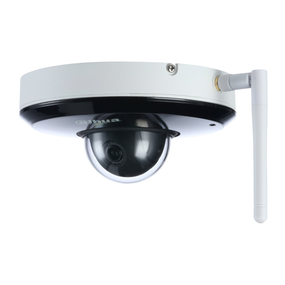
Speed Dome Installation Checking Accessories Before installation, check the accessories according to the packing list, and make sure all the components listed are included. Opening the Package Open the package, and take out the speed dome. See Figure 2-1. Figure 2-1 Network speed dome Reset Button and Memory Card Slot Turn over the speed dome, and then you can see the cover located on the bottom of the speed... -
Page 11: Reset Button
Figure 2-3 Reset button 2.3.1 Reset Button Reset button is for resetting the network system. Open the cover, press and hold the reset button for over 10 seconds, and then all the settings will be restored back to factory default. 2.3.2 Micro SD Card Micro SD card is for data storage. -
Page 12: Ceiling Mounting
Ceiling Mounting Installation Component Adopt installation position map for ceiling mounting. See Figure 3-1. Figure 3-1 Installation position map Speed Dome Installation 3.2.1 Installation Conditions Ceiling mounting is applicable to hard ceiling structure in both indoor and outdoor environments. Make sure: ... - Page 13 Figure 3-2 Sticking the installation position map Figure 3-3 Installation position requirement. Step 2 Knock the expansion bolts into the mounting holes and fix the mounting plate on the ceiling with the screws. See Figure 3-4. Figure 3-4 Fixing the mounting plate Ceiling Mounting 5...
- Page 14 Step 3 Pull the cables through the hole, and place the speed dome pedestal closely to the mounting plate. Step 4 Rotate the speed dome pedestal to the arrow shown on the speed dome edge, and then hang the speed dome on the mounting plate. See Figure 3-5. Figure 3-5 Rotating the speed dome pedestal Step 5...
-
Page 15: Wall Mounting
Wall Mounting Installation Component Adopt wall-mounted bracket and ceiling bracket for wall mounting. See Figure 4-1 for wall-mounted bracket, and see Figure 4-2 for ceiling bracket. Figure 4-1 Wall-mounted bracket Figure 4-2 Ceiling bracket Speed Dome Installation 4.2.1 Installation Conditions Wall mounting is applicable to hard wall structure in both indoor and outdoor environments. -
Page 16: Installation Steps
4.2.2 Installation Steps Step 1 Pull the speed dome cables through the ceiling mounting plate. See Figure 4-3. Figure 4-3 Pulling the speed dome cables Step 2 Place the speed dome cables closely into the wiring channel, and then install the mounting plate of speed dome on the ceiling mounting plate with the screws. - Page 17 Figure 4-4 Installing the mounting plate Step 3 Rotate the speed dome clockwise after the device pedestal is closely clung to the mounting plate, and then hang the speed dome on the mounting plate. See Figure 4-5. Figure 4-5 Hanging the speed dome Wall Mounting 9...
- Page 18 Step 4 Insert the screws into the holes on the side of mounting plate to secure the speed dome on the mounting plate. See Figure 4-6. Figure 4-6 Securing the speed dome on the mounting plate Step 5 Pull the speed dome cables and ceiling mounting plate flange through the wall-mounted bracket, and then secure the mounting plate and speed dome on the wall-mounted bracket with the screws.
- Page 19 Figure 4-8 Installation position requirement Step 6 Connect the corresponding cables of the speed dome to the wall cables, and then secure the wall-mounted bracket on the wall. And speed dome is installed. See Figure 4-9. Figure 4-9 Speed dome installed Wall Mounting 11...
-
Page 20: Appendix 1 Lightning Proof And Surge Protection
Appendix 1 Lightning Proof and Surge Protection Appendix 1.1 Outdoors This series of speed domes adopt TVS lightning protection technology. It can effectively prevent damages from various pulse signals below 6000V, such as sudden lightning. Take necessary safeguard measures when installing the speed dome in the outdoor environment according to your local electrical safety regulations. -
Page 21: Appendix 1.2 Indoors
Appendix 1.2 Indoors The yellow and green GND wire or GND screw of the speed dome should be reliably connected by several strands of copper wire with no less than 25mm²and indoor equipotential GND terminal. See Appendix figure 1-2 for indoor installation. Appendix figure 1-2 Indoor installation Lightning Proof and Surge Protection 13... -
Page 22: Appendix 2 12V Dc Cable Diameter And Transmission Distance
Appendix 2 12V DC Cable Diameter and Transmission Distance It is the recommended transmission distance for the fixed-sized cable with attrition rate lower than 10% of 12V DC. The Max. attrition rate of voltage allowed for DC power supply is 10%. The cables in the following table are all copper cables with electrical resistivity ρ... - Page 23 Appendix 3 Wire Gauge Reference Sheet Metric bare wire Bare wire cross diameter (mm) section (mm 0.050 0.00196 0.060 0.00283 0.070 0.00385 0.080 0.00503 0.090 0.00636 0.100 0.00785 0.110 0.00950 0.130 0.01327 0.140 0.01539 0.160 0.02011 0.180 0.02545 0.200 0.03142 0.230 0.04115 0.250...
Need help?
Do you have a question about the DH-SD1A404XB-GNR-W and is the answer not in the manual?
Questions and answers