Sign In
Upload
Download
Table of Contents
Contents
Add to my manuals
Delete from my manuals
Share
URL of this page:
HTML Link:
Bookmark this page
Add
Manual will be automatically added to "My Manuals"
Print this page
×
Bookmark added
×
Added to my manuals
Manuals
Brands
Dahua Manuals
Security Camera
DH-SD6C430U-HNI
Installation manual
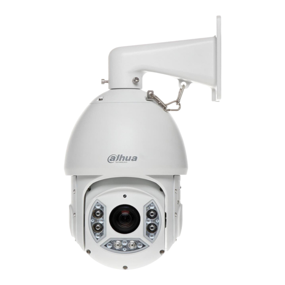
Dahua DH-SD6C430U-HNI Installation Manual
Ir intelligent speed dome
Hide thumbs
1
Table Of Contents
2
3
4
5
6
7
8
9
10
11
12
13
14
15
16
17
18
19
20
21
22
23
24
25
26
27
28
29
page
of
29
Go
/
29
Contents
Table of Contents
Bookmarks
Table of Contents
Table of Contents
Ir Intelligent Speed Dome Installation
Installation Preparation
Initial Setup
Dial Switch Setup (Analog Speed Dome)
Dial Switch Description
Parity Setup
Baud Rate Setup
Speed Dome Address Setup
Dial Switch Setup (HDCVI Speed Dome)
Dial Switch Description
HD/SD Video Format Setup
Baud Rate Setup
Speed Dome Address Setup
Reset and SD Card Installation (Network Speed Dome)
Speed Dome Installation
Overview
Installation Conditions
Dig Installation Holes
Speed Dome Installation
Hang Mount Installation
Installation Components
Installation
Installation Requirements
Installation Steps
Corner Mount Bracket
Component Installation
Installation
Installation Requirements
Installation Steps
Pole Mount Bracket
Installation
Installation Requirements
Installation Steps
Bracket Dimensions
Wall Mount Bracket
Hanging Mount Bracket (Multiple Lengths)
Corner Mount Bracket
Pole Mount Bracket
Appendix Ⅰ Thunder Proof and Surge Protection
Appendix Ⅱ about Rs485 Bus
RS485 Bus Main Feature
RS485 Bus Transmission Distance
The Problem in Practical Use
Advertisement
Quick Links
Download this manual
IR Intelligent Speed Dome Installation Manual
Version 1.1.4
Table of
Contents
Previous
Page
Next
Page
1
2
3
4
5
Advertisement
Table of Contents
Need help?
Do you have a question about the DH-SD6C430U-HNI and is the answer not in the manual?
Ask a question
Questions and answers
Related Manuals for Dahua DH-SD6C430U-HNI
Security Camera Dahua PTZ SDZ Series User Manual
Block camera (25 pages)
Security Camera Dahua DH-SD6323E-H Installation Manual
Intelligent speed dome (28 pages)
Security Camera Dahua D-SD6AL445XA-HNR Instruction Manual
Network speed dome & ptz camera (29 pages)
Security Camera Dahua DH-SD49225I-HC-S3 Installation Manua
4-inch ir speed dome (29 pages)
Security Camera Dahua DH-SD42C212T-HN Installation Manual
Intelligent speed dome (33 pages)
Security Camera Dahua DH-SD29204T-GN Installation Manual
Ir intelligent speed dome (21 pages)
Security Camera Dahua DH-SD22204I-GC Installation Manual
2-inch hdcvi speed dome (17 pages)
Security Camera Dahua DH-SD6AL245U-HNI-IR Installation Manual
Ir intelligent speed dome (43 pages)
Security Camera Dahua DH-SD6AL230F-HNI Installation Manual
Ir intelligent speed dome (43 pages)
Security Camera Dahua DH-SD6C230U-HNI Installation Manual
Ir intelligent speed dome (29 pages)
Security Camera Dahua DH-SD1A Installation Manual
Network speed dome (24 pages)
Security Camera Dahua DH-SD60230U-HNI Installation Manual
Intelligent speed dome (44 pages)
Security Camera Dahua DH-SD22204T-GN Installation Manual
2-inch network speed dome (16 pages)
Security Camera Dahua DH-SD49425GB-HNR Installation Manual
Network speed dome & ptz camera (27 pages)
Security Camera Dahua DH-SP-PIXX User Manual
(16 pages)
Security Camera Dahua DH-SD49225I-HC Installation Manual
4-inch ir speed dome (25 pages)
This manual is also suitable for:
Dh-sd6c230u-hni
Dh-sd6c225u-hni
Table of Contents
Print
Rename the bookmark
Delete bookmark?
Delete from my manuals?
Login
Sign In
OR
Sign in with Facebook
Sign in with Google
Upload manual
Upload from disk
Upload from URL


Need help?
Do you have a question about the DH-SD6C430U-HNI and is the answer not in the manual?
Questions and answers