Advertisement
Available languages
Available languages
Quick Links
Please Do Not Return This
Product to the Store!
Contact Escalade® Sports customer service department at:
Phone: 1-866-873-3528 Toll-Free!
Fax: 1-866-873-3533 Toll-Free!
E-mail: customerservice@escaladesports.com
Escalade® Sports products may be manufactured and/or licensed under the following patents.
6120397, 5816957, 5769744, 5119741, 4911085, 4717157, D460140, D420563, 8414431
Additional patents may be pending. One or more of the listed patents and/or pending patents may cover specific product.
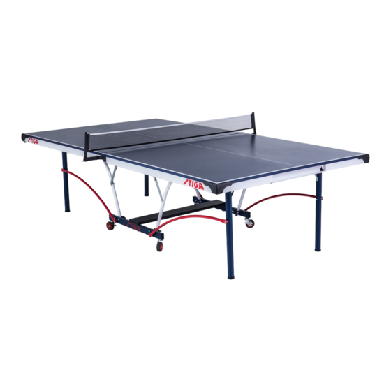
" E L I T E "
T A B L E T E N N I S T A B L E
MODEL NO.
T8624
2L-7627-00
Ó
2017 Escalade Sports
Advertisement

Related Manuals for Stiga ELITE T8624


Summary of Contents for Stiga ELITE T8624
- Page 1 “ E L I T E ” T A B L E T E N N I S T A B L E MODEL NO. T8624 Please Do Not Return This Product to the Store! Contact Escalade® Sports customer service department at: Phone: 1-866-873-3528 Toll-Free! Fax: 1-866-873-3533 Toll-Free! E-mail: customerservice@escaladesports.com...
- Page 2 P R E - A S S E M B L Y T I P S 1. Read this manual carefully before starting assembly. Read each step completely before beginning each step. 2. Some smaller parts may be shipped inside larger parts. Check inside all parts and cartons before assembling or ordering parts.
-
Page 3: Hardware Identifier
NOTE: Sorting your hardware ahead of time will speed up assembly time. Sort all your hardware now so it will be ready before you start assembly. HARDWARE IDENTIFIER 1/4-20 Nyloc 3/8-16 x 3 1/2 Hex Head Bolt Locknut (Qty. 4) (Qty. -
Page 4: Hardware Needed
HARDWARE NEEDED On the top of each page you will find a picture of the NOTE: Hardware Needed (to scale) along with the Quantity, Having a second person sort hardware and hold parts will speed up assembly time Key# and Description. You can lay the hardware on 3/8 Push Nut and make it easier to assemble your table. - Page 5 HARDWARE NEEDED 3/8-16 X 2 3/4 Hex Head Bolt 3/8-16 Locknut (Qty. 8) (Qty. 8) 2. Lay Support Plates (#43) on Caster Beam (#8) to line up holes, the distance between middle holes to side holes is different, see Front View of Figure 2. Attach Stop Spools (#12) and Support Plates (#43) to side of Caster Beam without logo with Bolts (#13) and Nuts (#28) as shown in Figure 2.
- Page 6 HARDWARE NEEDED CAUTION: READ AND FOLLOW ALL ASSEMBLY, OPERATING, AND SAFETY INSTRUCTIONS CAREFULLY. AT LEAST TWO (2) 1/4-20 X 3 1/4 Carriage Bolt ADULTS ARE NEEDED TO PUT THIS TABLE TOGETHER! (Qty. 4) 1/4-20 Wing Nut (Qty. 4) 3. Attach Wood Bottom Board (#15) to Caster Beam Assemblies (#8) as shown in Figure 3.
-
Page 7: Top View
HARDWARE NEEDED 3/8-16 x 3 1/2 Hex Head Bolt 3/8-16 (Qty. 4) Locknut 3/4" Long Spacer 3/8" Plastic (Qty. 4) (Qty. 4) Washer (Qty. 8) 4. Attach Strut Tubes (#17) and Red Linkages (#16) to Caster Beam Assemblies (#8) as shown in Figure 4. a) If necessary loosen Bolts (#13) and Nuts (#28) so that Strut Tube (#17) can fit between Support Plate (#43) and Caster Beam (#8) as shown in the Top View and Figure 4. - Page 8 Table top can be set on two saw horses. Although this will make NOTICE assembly easier it is not necessary to complete assembly. Always use WHEN ASSEMBLING TABLE, IT IS EXTREMELY IMPORTANT THAT THE U-CLIPS (#22) BE shipping container to protect the painted surface of the table top. TURNED AS SHOWN HERE.
- Page 9 HARDWARE NEEDED 8. Rotate U-support (#21) that is on bottom of Table Top until you see the screw holes in the slots of U-clips (#22). If necessary Slide U-support (#21) #8-32 X 1 1/4 side to side and back and forth to see holes. See Figure 6 & Detail B. Sheet Metal Screw (Qty.
- Page 10 HARDWARE NEEDED NOTICE IF USING AN ELECTRIC SCREWDRIVER PLEASE SET AT LOW TORQUE AND USE CAUTION BECAUSE YOU COULD OVER-TIGHTEN THE #8 X 9/16 Screw HARDWARE AND STRIP SCREW IN WOOD DOING IRREPARABLE (Qty. 28) DAMAGE TO THE TABLE. DO NOT OVER TIGHTEN SCREWS! 10.
- Page 11 Note: You Will Need one hinge in position A and one in position C for the next page. Hinges If you want to see a video on how to rotate hinges go to: NOTE: http://www.escaladesports.com/customer-service/instruction-videos are universal and can be rotated into either position A or C. See Figure 8A. Scan with your Smartphone/Tablet: 1.
- Page 12 HARDWARE NEEDED NOTICE IF USING AN ELECTRIC SCREWDRIVER PLEASE SET AT LOW TORQUE AND USE CAUTION BECAUSE YOU COULD OVER-TIGHTEN THE HARDWARE AND STRIP SCREWS IN WOOD #8 X 9/16 Screw DOING IRREPARABLE DAMAGE TO THE TABLE. DO NOT OVER TIGHTEN SCREWS! (Qty.
- Page 13 HARDWARE NEEDED 1/4" Plastic #10-24 X 1/2 Phillips #10-24 Washer 1/4-20 X 2 1/2” Hex Head Bolt 1/4-20 Nyloc Locknut Pan Head Screw Locknut (Qty. 4) (Qty. 2) (Qty. 2) (Qty. 2) (Qty. 2) 12. Attach legs (#19) to Mounting Brackets (#20 & 25) with Hex Bolt (#24), two Plastic Washers (#38) and Locknut (#34). Attach leg brace to Leg Mounting Bracket (#25) with Phillips Head Screw (#29) and Locknut (#33) as shown in Detail F.
- Page 14 Screws (#5). See Figure 11 & Detail H. Note: All Indentations guides in table top are small so look closely. Stiga logo on this side Stiga logo on this side Figure...
- Page 15 17. Attach Corner Protectors to Table Top using Screw (#5) as shown in Detail J & K. HARDWARE NEEDED #8 X 9/16 Screw 18. Attach Net Plate (#45) as shown in Detail L & Detail M. Make sure the Nut (Qty.
- Page 16 20. Attach Table Top Assembly to Base Assembly as shown in Figure 13. Pivot Strut Tubes (#17) up as shown; then, with AT LEAST TWO (2) ADULTS ARE NEEDED TO at least one adult on each side of Table Top, lift top and COMPLETE THE REST OF THIS ASSEMBLY! WHEN ASSEMBLING TOPS TO BASE, HANDLE TOP align ends of U-support tube (#21) with tops of Strut Tubes...
- Page 17 HARDWARE NEEDED DO NOT OPEN THE TABLE TO PLAYING POSITION UNTIL BOTH TOPS ARE INSTALLED! DO NOT LEAVE TABLE STANDING UNATTENDED. IT COULD BE 1/4-20 X 1 1/2 Phillips 1/4" Plastic KNOCKED OVER CAUSING SERIOUS 1/4-20 Locknut Truss Head Screw Washer BODILY INJURY OR PROPERTY DAMAGE.
- Page 18 HARDWARE NEEDED #8 X 9/16 1/4-20 X 2 1/2” Hex Head Bolt Screw 1/4-20 Locknut 3/8" Long Spacer (Qty. 2) (Qty. 2) (Qty. 2) (Qty. 2) 22. Secure U-support tube (#21) to Strut Tubes (#17) with two Screws (#5) as shown in Figure 15.
- Page 19 OPENING AND CLOSING INSTRUCTIONS CAUTION: EXERCISE CAUTION IN OPENING/CLOSING TABLE. SMALL CHILDREN, OR CHILDREN NOT PROPERLY INSTRUCTED IN ITS USE, MUST NOT BE ALLOWED TO OPEN/CLOSE TABLE. IMPROPER HANDLING AND MISUSE CAN RESULT IN SERIOUS INJURY OR DAMAGE. DO NOT CLIMB, STAND, OR JUMP ON TABLE. MOISTURE AND CONDENSATION WILL DAMAGE PLAYING SURFACE OF THIS TABLE.
- Page 20 by firmly gripping the vertical net post within height adjustment slot 3. Storage Caution: To prevent damage to the net system and/or table top, the post assembly must be pivoted toward side of table before lifting table tops to storage position. Loosen knob and pivot net post toward table side as far as it will go.
- Page 21 Replacement Parts List for Model Number T8624 Key# Part # T8624 Description Qty. 4A-8247-00 3/4" Indented Top - Blue 2S-4644-02 Side Rail - Right Hand 2S-4645-02 Side Rail - Left Hand 2S-5137-05 Ball Holder Rail 1B-4082-99 #8 x 9/16" Sheet Metal Screw 3M-6273-00 U-Support Clip (Plastic) 3M-1027-00...
-
Page 22: One-Year Limited Warranty
ONE YEAR LIMITED WARRANTY This consumer warranty extends to the original consumer purchase of any ESCALADE ® SPORTS Product (hereinafter referred as the "Product"). WARRANTY DURATION: This Product is warranted to the original consumer purchase of a period of one (1) year from the original purchase. - Page 23 “ E L I T E ” M E S A D E T E N I S D E M E S A NÚMERO DE MODELO T8624 Por favor no regrese este producto a la tienda! Contacte al departamento de servicio al cliente de Escalade® Sports: Teléfono:1-866-873-3528 ¡Sin costo alguno! Fax:1-866-873-3533 ¡Sin costo alguno! E-mail:tabletennis@escaladesports.com...
- Page 24 C O N S E J O S A N T E S D E I N S T A L A C I Ó N 1. Lea este manual cuidadosamente antes de empezar a ensamblar. Lea completamente cada uno de los pasos antes de empezar a ensamblar cada paso.
- Page 25 Ordenando las tuercas y tornillos antes de empezar reducirá el tiempo de instalación. Separe las NOTA: partes ahora para que este listo antes de empezar la instalación. IDENTIFICADOR DE TORNILLOS 1/4-20 Tuerca 3/8-16 x 3 1/2 Tornillo de Cabeza Hexagonal de Seguridad (Cant.
- Page 26 NECESITA: En la parte superior de cada página encontrará un dibujo del las NOTA: tuercas y tornillos necesarios (a escala) junto con la cantidad, Teniendo un ayudante para detener y ordenar las partes, al igual que las tuercas y número de clave y descripción. Puede colocar las partes sobre el CONSEJOS DE 3/8 Contratuerca tornillos reducirá...
- Page 27 NECESITA: 3/8-16 X 2 3/4 Tornillo 3/8-16 Tuerca (Cant. 8) (Cant. 8) 2. Coloque las placas de soporte (#43) en el Carril (#8) para alinear los orificios, la distancia entre los orificios centrales de los orificios laterales es diferente, vea la Figura 2 y la Vista Frontal. Coloque los Carretes (#12) y las Placas de Soporte (#43) del lado del Carril sin el logotipo, con los Tornillos (#13) y las Tuercas (#28) pero NO los apriete completamente.
- Page 28 NECESITA: PRECAUCIÓN: LEA Y SIGA TODAS LAS INSTRUCCIONES DEL ENSAMBLADO, LAS OPERACIONES Y LAS INSTRUCCIONES 1/4-20 X 3 1/4 Tornillo de Carruaje DE SEGURIDAD. POR LO MENOS SE REQUIERE DE DOS (2) (Cant. 4) ADULTOS PARA ENSAMBLAR LA MESA! 1/4-20 Tuerca de Mariposa (Cant.
- Page 29 NECESITA: 3/8-16 x 3 1/2 Tornillo 3/8-16 (Cant. 4) Tuerca 3/4" Separador 3/8" Rondana de (Cant. 4) (Cant. 4) Plástico (Cant. 8) 4. Una los Tubos Estructurales (#17) y los Tubos Conectores (#16) a los Carriles con Llantas (#8) como están mostrados en la Figura 4. a) Si es necesario afloje los Tornillos (#13) y las Tuercas (#28) para que el Tubo Estructural (#17) pueda caber entre la Placa de Soporte (#43) y Carril con Llantas (#8) como esta mostrado en la Vista de arriba y la Figura 4.
- Page 30 La superficie de la mesa se puede poner sobre de dos caballetes de NOTICE AVISO carpintería. Aunque esto hará más fácil ensamblar la mesa, no es necesario para que pueda completar el ensamblado. Siempre utilice los cartones del CUANDO ENSAMBLE LA MESA, ES EXTREMADAMENTE IMPORTANTE QUE TODAS LAS empaque donde venía la mesa, para proteger la superficie de la mesa pintada.
- Page 31 NECESITA: 8. Gire el tubo de soporte "U" (#21) que se encuentra en la base del tablero, hasta que vea los orificios atra vez de las abrazaderas en “U” (#22) donde van los tornillos. Si es necesario deslice el tubo de soporte "U" (#21) de lado a lado y hacia atrás y adelante para ver los #8-32 X 1 1/4 Tornillo para Lamina orificios.
- Page 32 NECESITA: AVISO SI USA UN DESTORNILLADOR ELÉCTRICO, DEBE USARLO EN POTENCIA BAJA Y TENER MUCHO CUIDADO DE NO AJUSTAR EN EXCESO YA QUE #8 X 9/16 Tornillo DAÑARÍA LA MESA CON LOS TORNILLOS, Y LE CAUSARÍA DAÑOS IRREPARABLES. NO SOBRE APRIETE LOS TORNILLOS! (Cant.
- Page 33 Necesitará una bisagra en la posición A, y una en la posición C. Las bisagras NOTA: son universales y pueden rotarse en posición A o C. Ver Figura 8A. 1. Determine en qué posición están sus bisagras, si tiene una bisagra en la posición A y una en posición C continúe en la página siguiente.
- Page 34 NECESITA: AVISO SI USA UN DESTORNILLADOR ELÉCTRICO, DEBE USARLO EN POTENCIA BAJA Y TENER #8 X 9/16 Tornillo MUCHO CUIDADO DE NO AJUSTAR EN EXCESO YA QUE DAÑARÍA LA MESA CON LOS TORNILLOS, Y LE CAUSARÍA DAÑOS IRREPARABLES. NO SOBRE APRIETE LOS TORNILLOS! (Cant.
- Page 35 NECESITA: 1/4" Rondana #10-24 Tuerca #10-24 X 1/2 1/4-20 Plastico 1/4-20 X 2 1/2” Tornillo de Cabeza Hexagonal de Seguridad Tuerca de Seguridad Tornillo Phillips (Cant. 4) (Cant. 2) (Cant. 2) (Cant. 2) (Cant. 2) Instale las patas (#19) al los Soportes de Montaje (#20 & 25) con el Tornillo de Cabeza Hexagonal (#24), dos Rondanas de Plástico (#38) y la Tuerca de Seguridad (#34).
- Page 36 Tornillos (#5). Ver la Figura 11 y el Detalle H. NOTA: Los orificios de guía son muy pequeños ponga atención donde están los orificios. LOGO DE STIGA DE ESTE LADO LOGO DE STIGA DE ESTE LADO Figura...
- Page 37 NECESITA: 17. Coloque los Protectores de Esquinas (#40) a la mesa usando un tornillo (#5) como se muestra en el Detalle J y Detalle K. Tornillo #8 X 9/16 (Cant. 12) 18. Coloque la Placa con Tuerca (#45) como se muestra en el Detalle L y M. Asegurese que la placa este nivelada con el rincón de la mesa, y asegurese de usar los tres orificios superiores en la placa.
- Page 38 20. Instale el Tablero a la base, como lo muestra en la Figura 13. ADVERTENCIA: Gire los Tubos Estructurales (#17) hacia arriba como esta mostrado; después con al menos un adulto en cada lado POR LO MENOS SE REQUIEREN DOS (2) ADULTOS de la mesa, levante y alinie los extremos del Tubo de Soporte- PARA TERMINAR EL RESTO DEL ENSAMBLADO! CUANDO ENSAMBLE LOS TABLEROS A LA BASE,...
- Page 39 NECESITA: ADVERTENCIA: NO ABRA LA MESA EN LA POSICIÓN DE JUEGO, HASTA QUE AMBAS MITADES DE LA MESA ESTÉN INSTALADAS DEJE LA MESA LEVANTADA SOLA. 1/4-20 X 1 1/2 PODRÍA CAERSE SOBRE ALGUIEN 1/4" Rondana Tornillo Phillips 1/4-20 Tuerca CAUSANDO HERIDAS SERIAS Ó DAÑO de Plástico (Cant.
- Page 40 NECESITA: #8 X 9/16 1/4-20 X 2 1/2” Tornillo Tornillo 1/4-20 Tuerca 3/8" Separador (Cant. 2) (Cant. 2) (Cant. 2) (Cant. 2) 22. Atornille el Tubo del Soporte-U (#21) a los Tubos Estructurales (#17) con los dos Tornillos (#5) como se muestra en Figura 15. Alinie los orificios de los tubos de Soporte-U con los ADVERTENCIA: Tubos Estructurales e inserte los Tornillos (#5) en los orificios de los Tubos Estructurales (#17).
- Page 41 INSTRUCCIONES PARA ABRIR Y CERRAR PRECAUCIÓN: PONGA ATENCIÓN AL ABRIR Y AL CERRAR LA MESA. MENORES DE EDAD QUE NO SABEN EL USO APROPIADO DE LAS INSTRUCCIONES NO SE LES DEBE PERMITIR ABRIR Y CERRAR LA MESA. EL MANEJO O USO INCORRECTO DE LA MESA PUEDE CAUSAR LESIONES GRAVES O DAÑOS MATERIALES.
- Page 42 2. Ajustes A - Ajuste la tensión general de la red aflojando levemente la manija y DESCRIPCION DEL moviendo el soporte. Ajuste suavemente la manija. El soporte deberá estar en escuadra con la mesa cuando haya llegado al tope. (Ver SISTEMA DE RED Descripción del sistema de red) B - Ajuste la tensión de la cuerda con la cadena de cuentas a cada...
- Page 43 Lista de partes para el modelo T8624 # de Parte # de Parte Descripción Cant. # de Ref. T8624 T8624 4A-8247-00 Tablero de 3/4" - Azul 2S-4644-02 Riel Mano Derecha 2S-4645-02 Riel Mano Izquierda 2S-5137-05 Riel con Recipiente de pelotas 1B-4082-99 #8 X 9/16 Tornillo Para Lamina de Metal 3M-6273-00...
-
Page 44: Garantía Limitada Por Un Año
GARANTÍA LIMITADA POR UN AÑO ® Esta garantía es aplicable para consumidores de la compra original de cualquier producto ESCALADE SPORTS (en adelante denominado el "Producto"). DURACIÓN DE LA GARANTÍA: Se garantiza este Producto al comprador original por un período de un (1) año a partir de la fecha de compra. COBERTURA DE LA GARANTÍA: ESCALADE SPORTS le garantiza al comprador original que cualquier producto de su fabricación está...
Need help?
Do you have a question about the ELITE T8624 and is the answer not in the manual?
Questions and answers