Table of Contents
Advertisement
Quick Links
Bench type, RS232/USB computer interface
TDS ( Total Dissolved Solids )
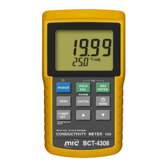
CONDUCTIVITY METER
Model : BCT-4308
OPERATION MANUAL
PLEASE READ THIS MANUAL CAREFULLY BEFORE OPERATION
Hagavish st. Israel 58817 Tel: 972 3 5595252, Fax: 972 3 5594529
Your purchase of this
B E N C H
CONDUCTIVITY METER
marks a step forward
for you into the field of
precision measurement.
Although this METER is
a complex and delicate
instrument, its durable
structure
many years of use if
p r o p e r
t e c h n i q u e s
developed. Please read
t h e
instructions
and always keep this
manual
reach.
MRC.1.22
T Y P E
will
allow
o p e r a t i n g
a r e
f o l l o w i n g
carefully
within
easy
mrc@mrclab.com
Advertisement
Table of Contents

Subscribe to Our Youtube Channel
Related Manuals for MRC BCT-4308


Summary of Contents for MRC BCT-4308
- Page 1 Bench type, RS232/USB computer interface TDS ( Total Dissolved Solids ) CONDUCTIVITY METER Model : BCT-4308 Your purchase of this B E N C H T Y P E CONDUCTIVITY METER marks a step forward for you into the field of precision measurement.
-
Page 2: Table Of Contents
TABLE OF CONTENTS 1. FEATURES..............1 2. SPECIFICATIONS............2 2-1 General Specifications.......... 2 2-2 Electrical Specifications........4 3. FRONT PANEL DESCRIPTION........5 4. CONDUCTIVITY/TDS MEASURING and CALIBRATION PROCEDURE........7 4-1 uS, mS measurement...........8 4-2 TDS ( PPM ) measurement........9 4-3 Calibration............10 5. -
Page 3: Features
1. FEATURES * Professional bench type meter with large size LCD display with green color backlight, easy reading. * One meter for two purpose operation : Conductivity and TDS ( Total dissolved solids ), measurement. * Conductivity : 200 uS/2 mS/20 mS/200 mS. * Measurement unit can select uS/mS ( conductivity ) or ppm ( TDS ) * Conductivity measurement can select Temp. -
Page 4: Specifications
2. SPECIFICATIONS 2-1 General Specifications Circuit Custom one-chip of microprocessor LSI circuit. Display LCD size : 82 mm x 61 mm. * with green color backlight. Measurement * Conductivity ( uS, mS ) * TDS ( Total Dissolved Solids, PPM ) * Temperature ( ℃... - Page 5 Operating Main instrument 0 to 50 ℃ Temperature Probe 0 to 60 ℃ Operating Less than 80% R.H. Humidity Power Supply DC 1.5 V battery ( UM3 ) x 8 PCs, ( Heavy duty type ). DC 9V adapter input. @ AC/DC power adapter is optional.
-
Page 6: Electrical Specifications
2-2 Electrical Specifications (23± 5 ℃ Conductivity ( uS, mS ) Range Measurement Resolution Accuracy 200 uS 0 to 200.0 uS 0.1 uS 2 mS 0.2 to 2.000 mS 0.001 mS ± (2% F.S.+1d) 20 mS 2 to 20.00 mS 0.01 mS * F.S. -
Page 7: Front Panel Description
3. FRONT PANEL DESCRIPTION Fig. 1-1... - Page 8 Fig. 1-2 3-1 Display 3-2 Power Button ( LCD Backlight Button ) 3-3 HOLD Button ( ESC Button ) 3-4 REC Button ( Enter Button ) 3-5 Zero Button 3-6 Function Button ( Range Button ) 3-7 Send Button ( Clock Button ) 3-8 SET Button ( Logger Button ) Up Button ▲...
-
Page 9: Conductivity/Tds Measuring And Calibration Procedure
4. CONDUCTIVITY/TDS MEASURING and CALIBRATION PROCEDURE The meter default function are following : * The display unit is set to conductivity ( uS, mS ). * The temperature unit is set to ℃ * Temp. compensation factor is set to 2.0% per C. * Auto range. -
Page 10: Us, Ms Measurement
4-1 uS, mS measurement 1) Prepare the Conductivity Probe ( included, CDPB-03 ), install the " Probe Plug " ( 4-1, Fig. 2 ) into the " CD Socket " ( 3-11, Fig. 1 ). 2) Power on the meter by pressing " Power Button " ( 3-2, Fig. -
Page 11: Tds ( Ppm ) Measurement
Change the Temp. unit to ℉ If intend to change the Temp. unit from , please ℃ ℉ refer page 17, chapter 6-6 ( Temp. Unit Default Setting ) Change the Temp. Coefficient Factor The default Temp. compensation factor value of the measurement solution is to 2.0% per . -
Page 12: Calibration
4-3 Calibration 1) Prepare the standard conductivity solution ( optional ) For example : 2 mS range calibration solution : 1.413 mS Conductivity Standard Solution, CD-14 200 uS range calibration solution : 80 uS Conductivity Standard Solution 20 mS range calibration solution : 12.88 mS Conductivity Standard Solution or other Conductivity Standard Solution 2) Install the "... -
Page 13: Data Hold, Data Record, Data Logger
* If only intend to make the one point calibration, just execute the 2 mS range ( 1.413 mS Cal. ) is enough. * Multi-points calibration procedures should execute the 2 mS range ( 1.413 mS Cal. ) calibration at first, then make other ranges (20 uS range, 20 mS range or 200 mS range ) calibration procedures following if necessary. - Page 14 b)Press the " REC Button " ( 3-4, Fig. 1 ) again, the " REC MIN " symbol along with the minimum value will appear on the display. If intend to delete the minimum value, just press the " Hold Button " ( 3-3, Fig. 1 ) once, then the display will show the "...
- Page 15 Manual Data Logger ( Sampling time set to 0 second ) Press the " Logger Button " ( 3-8, Fig. 1 ) once will save the data one time into the memory. Beeper will sound and the upper display will show "...
-
Page 16: Advanced Adjustment Procedure
6. ADVANCED ADJUSTMENT PROCEDURES Under do not execute the Datalogger function, press the " SET Button " ( 3-8, Fig. 1 ) continuously at least two seconds will enter the " Advanced Setting " mode, press the " SET Button " ( 3-8, Fig. 1 ) once a while in sequence to select the 13 main function, the display will show : SPACE... -
Page 17: Check Memory Space
6-1 Check memory space When the display show " SPACE " To check the balance data numbers that exist into the memory ( allow the balance memorize data no. ). @ The bottom value XXXXX is the balance data numbers, for example XXXXX=15417. -
Page 18: Set Date/Time
6-3 Set Date/Time ( Year/Month/Date, Hour/Minute/ Second ) When the upper display show " dAtE " 1) Use the " Button " ( 3-9, Fig. 1 ) or " Button " ▲ ▼ ( 3-10, Fig. 1 ) to adjust the value ( Setting start from Year value ). -
Page 19: Auto Power Off Management
Remark : The adjusted value will be flashed. 2) After set all the sampling time value ( Hour, Minute, Second ), press the " SET Button " ( 3-8, Fig. 1 ) once will save the sampling value with default then the screen will jump to "... -
Page 20: Set Cd Temperature Compensation Factor
2) After Display unit is selected to " C " or " F ", press the " Enter Button " ( 3-4, Fig. 1 ) will save the setting function with default. 6-7 Set CD temperature compensation factor When the lower display show " PEr C " 1) This function only for the Conductivity ( TDS ) mode of adjusting the probe's Temp. -
Page 21: Send The Data Out From The Meter
7. SEND THE DATA OUT FROM THE METER 1) If intend to send the data out from the meter, it should exit the " Hold function " and the " Record function " first. The display should be not show the "... - Page 22 * Exit the Data logger function and execute the Data logger function again will generate the second Memory " Block " again. Block 1 Data 1 Data X ↓ Block 2 Data X+1 Data Y ↓ ........↓ Block 250 Data Z Data 16,000 3) Until the desired Memory Block no.
-
Page 23: Rs232 Pc Serial Interface
Remarks : If intend to load the data to the computer, should connect the RS232 cable ( optional, model : UPCB-02) or the USB cable ( optional, model : USB-01 ) and apply the Data Logger software ( optional, Model : SW-DL2005 ). - Page 24 The 16 digits data stream will be displayed in the following format : D15 D14 D13 D12 D11 D10 D9 D8 D7 D6 D5 D4 D3 D2 D1 D0 Each digit indicates the following status : Start Word = 02 When send the upper display data = 1 When send the lower display data = 2 D12, D11 Annunciator for Display...
-
Page 25: Battery Replacement
9. BATTERY REPLACEMENT 1) When the left corner of LCD display show " ", it is necessary to replace the batteries ( UM3/1.5 V x 8 PCs ). 2) Slide the " Battery Cover " ( 3-16, Fig. 1 ) away from the instrument and remove the batteries. -
Page 26: Optional Accessories
11. OPTIONAL ACCESSORIES RS232 cable * Computer interface cable. UPCB-02 * Used to connect the meter to the computer ( COM port ). USB cable * Computer interface cable. USB-01 * Used to connect the meter to the computer ( USB port ). Data Logger * Software the used to download software...
Need help?
Do you have a question about the BCT-4308 and is the answer not in the manual?
Questions and answers