Sign In
Upload
Download
Table of Contents
Contents
Add to my manuals
Delete from my manuals
Share
URL of this page:
HTML Link:
Bookmark this page
Add
Manual will be automatically added to "My Manuals"
Print this page
×
Bookmark added
×
Added to my manuals
Manuals
Brands
Modern Forms Manuals
Fan
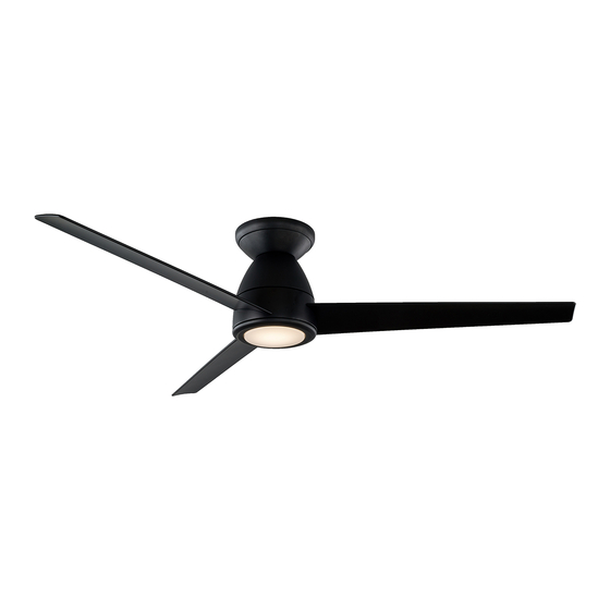
Tip Top 52
Installation instructions manual
Modern Forms Tip Top 52 Installation Instructions Manual
Hide thumbs
1
2
3
4
5
6
Table Of Contents
7
8
9
10
11
12
13
14
15
16
17
18
19
20
21
22
23
24
25
26
27
28
29
30
31
32
33
34
35
36
page
of
36
Go
/
36
Contents
Table of Contents
Troubleshooting
Bookmarks
Table of Contents
Table of Contents
Mounting Options
Installing the Mounting Bracket
Attaching the Fan Blade
Adding the Decorative Trim Ring
Hanging the Fan
Making the Electrical Connections
Installing the Optional Wall Control
Finishing the Installation
Installing Adapter Plate
Installing the Luminaire Module
Controlling the Fan
Reset
Breeze Mode
Application
Accessories
Troubleshooting
Advertisement
Quick Links
Download this manual
TipTop
Installation Instructions
works with the
Google Assistant
Table of
Contents
Previous
Page
Next
Page
1
2
3
4
5
Advertisement
Table of Contents
Need help?
Do you have a question about the Tip Top 52 and is the answer not in the manual?
Ask a question
Questions and answers
Related Manuals for Modern Forms Tip Top 52
Fan Modern Forms Torque Installation Instructions Manual
(36 pages)
Modern Forms Torque FR-W2204-70 / 58 Manual
(article)
Fan Modern Forms Tip Top 44 Installation Instructions Manual
(36 pages)
Fan Modern Forms VOX FLUSH FH-W1802-26L Installation Instructions Manual
Vox flush 26” & 38” (24 pages)
Fan Modern Forms VORTEX FR-W1810 Installation Instructions Manual
(28 pages)
Modern Forms CARVE 60 / 72 (FR-D2504) Manual
(article)
Fan Modern Forms F-WCBT-WT Installation Instructions
Smart fans (2 pages)
Modern Forms F-RCBT-WT - Fan Operation Manual
(article)
Fan Modern Forms Axis 52 Flush Installation Instructions Manual
(38 pages)
Fan Modern Forms Zephyr 62 Installation Instructions Manual
(40 pages)
Fan Modern Forms AXIS FR-W1803-52L Installation Instructions Manual
(32 pages)
Modern Forms Zephyr 5 FR-W2401-62L Manual
(article)
Modern Forms Vox FR-W1802 Manual
(article)
Fan Modern Forms WINDFLOWER FR-W1815-60L Installation Instructions Manual
(32 pages)
Modern Forms BOLO FR-W2501-56L Manual
(article)
Modern Forms Windflower FR-W1815 Manual
(article)
This manual is also suitable for:
Tip top 44
Fh-w2004-52l-ba
Fh-w2004-44l-ba
Table of Contents
Print
Rename the bookmark
Delete bookmark?
Delete from my manuals?
Login
Sign In
OR
Sign in with Facebook
Sign in with Google
Upload manual
Upload from disk
Upload from URL


Need help?
Do you have a question about the Tip Top 52 and is the answer not in the manual?
Questions and answers