
Related Manuals for Exsys EX-6131


Summary of Contents for Exsys EX-6131
- Page 1 Anleitung EX-6131 Ethernet zu 1x Seriell RS-232 & 1x Seriell RS-422/485 Ethernet to 1x Serial RS-232 & 1x Serial RS-422/485 Vers. 1.0 / 30.11.21 Manual...
-
Page 2: Table Of Contents
Layout ······················································································································ 16 Connections & LED‘s······························································································· 16-17 Hardware Installation ·························································································18 Configuration of the Device Server ·······································································19 VCOM Admin Utility ····················································································· 20-24 DIP-Switch Settings ···························································································25 Cleaning ··········································································································26 Technical Information ·························································································26 Technical Drawing ·····························································································26 © Copyright 2021 by EXSYS Vertriebs GmbH. All Rights Reserved... -
Page 3: Beschreibung
Unterstützt 15KV ESD-Schutz für alle serielle Signale • Unterstützt 5V über seriellen Anschluss • Zertifiziert für 2. Lieferumfang Bevor Sie den EX-6131 in Ihr Netzwerk einbinden, überprüfen Sie bitte zuerst den Inhalt der Lieferung: • EX-6131 • Netzteil (5V/4A) •... -
Page 4: Aufbau, Anschlüsse & Led's
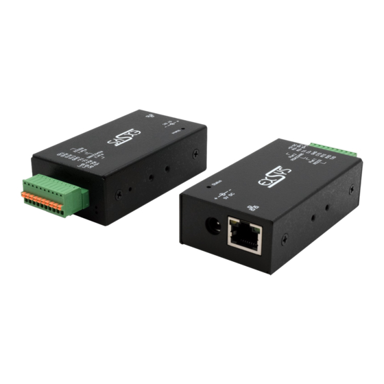
3.2 Anschlüsse & LED‘s 10-Pin Terminal Block: Port 2 (RS422/485) Port 1 (RS232) Beschreibung RS-232 Mode RS-422 & RS-485 4-Draht Modi RS-485 2-Draht Modi DATA- DATA+ Port 2 Port 1 © Copyright 2021 by EXSYS Vertriebs GmbH. All Rights Reserved... - Page 5 Blinken: Die serielle Schnittstelle sendet Daten Grün (oben) Aus: Die serielle Schnittstelle sendet keine Daten RXD LED Blinken: Die serielle Schnittstelle empfängt Daten Grün (unten) Aus: Die serielle Schnittstelle empfängt keine Daten © Copyright 2021 by EXSYS Vertriebs GmbH. All Rights Reserved...
-
Page 6: Hardware Installation
4. Schließen Sie jetzt das im Lieferumfang enthaltene 5V Netzteil an die dafür vorhergesehene 5V Buchse der EX-6131 an. Warten Sie etwa 25-30 Sekunden bis die Status LED anfängt zu blin- ken. Sobald diese LED blinkt, ist das Gerät betriebsbereit. -
Page 7: Konfiguration Des Geräteserver
Serial Interface: Port 1: RS-232 / Port 2: RS-485 2-Draht Falls Sie den EX-6131 auf „Werkseinstellung“ zurücksetzen möchten, dann drücken und halten Sie den Reset Schalter für ca. 3-5 Sekunden gedrückt. Die Status LED erlischt und fängt ein paar Sekunden später wieder an zu blinken. -
Page 8: Vcom Admin Utility
Administrator ausführen“). Klicken Sie auf Remote Device Management > ADD Device > Search Nachdem der EX-6131 gefunden wurde, klicken Sie auf Cancel, um die Suche abzubrechen. Klicken Sie auf OK, um den EX-6131 hinzuzufügen. © Copyright 2021 by EXSYS Vertriebs GmbH. All Rights Reserved... - Page 9 Gerät zuzuordnen, klicken Sie auf COM Mapping > Add COM > OK Um die COM-Port-Nummer zu ändern, klicken Sie auf COM Mapping > Modify COM Der COM3 & COM4 wurde nun hinzugefügt! © Copyright 2021 by EXSYS Vertriebs GmbH. All Rights Reserved...
- Page 10 Schnittstelle auf andere Werte als die Standardwerte ändern (z.B. Device Description, Pass- word, ...), müssen Sie sich zuerst am Device Server anmelden (das Standardpasswort hierfür "system"). Klicken Sie auf Remote Device Management > Login © Copyright 2021 by EXSYS Vertriebs GmbH. All Rights Reserved...
- Page 11 Klicken Sie auf Remote Device Management > (Doppelklick auf das ausgewählte Element in der Liste) > Serial > (Doppelklick auf den Port in der Liste) > Das gewünschte Interface auswählen > OK Doppelklick Doppelklick © Copyright 2021 by EXSYS Vertriebs GmbH. All Rights Reserved...
- Page 12 > Open in Browser und geben Sie folgende Anmeldedaten ein: User Name: admin Password: system Klicken Sie auf Port Config > Port 1 > Operation Mode > Apply > Save & Restore © Copyright 2021 by EXSYS Vertriebs GmbH. All Rights Reserved...
-
Page 13: Dip-Schalter Einstellungen
Deutsch 7. DIP-Schalter Einstellungen Es gibt einen 4-Pin DIP-Schalter im inneren auf der Platine der EX-6131. Hierzu müssen Sie die zwei Schrauben auf den Seiten der EX-6131 herausschrauben und das obere Gehäuse lösen. In den meisten Fällen müssen Sie an dem DIP-Schalter keine Änderungen vornehmen! Der DIP- Schalter ist bei Werksauslieferung auf „OFF“... -
Page 14: Reinigung
0° bis 60° Celsius Lagertemperatur: -20° bis 75° Celsius Rel. Luftfeuchtigkeit: 5% bis 95% Schutzklasse: IP30 Stromversorgung: +5V/4A Abmessung: 82,00 x 46,20 x 25,00 mm Gewicht: 540g 10. Technische Zeichnung © Copyright 2021 by EXSYS Vertriebs GmbH. All Rights Reserved... -
Page 15: Description
Support 15KV ESD-Protection for all serial Signals • Support 5V over serial Connector • Certificate for 2. Extent of Delivery Before you integrate the EX-6131 into your network, you should first check the contents of the delivery: • EX-6131 • Power Supply (5V/4A) •... -
Page 16: Layout, Connections & Led's
3.2 Connections & LED‘s 10-Pin Terminal Block: Port 2 (RS422/485) Port 1 (RS232) Description RS-232 Mode RS-422 & RS-485 4-wire Mode RS-485 2-wire Mode DATA- DATA+ Port 2 Port 1 © Copyright 2021 by EXSYS Vertriebs GmbH. All Rights Reserved... - Page 17 Off: The Serial Port is not sending out any data RXD LED Blinking: The Serial Port is receiving data Green (below) Off: The Serial Port is not receiving any data © Copyright 2021 by EXSYS Vertriebs GmbH. All Rights Reserved...
-
Page 18: Hardware Installation
1. Install the EX-6131 on a mounting rail by using the DIN rail kit or on a wall by using the wall mounting bracket which both are includes in the extend of delivery. -
Page 19: Configuration Of The Device Server
Port 1: RS-232 / Port 2: RS-485 2-wire If you want to reset the EX-6131 to "Factory Settings", then press and hold the reset button for approx. 3-5 seconds. The status LED goes out and starts flashing again a few seconds later. -
Page 20: Vcom Admin Utility
EX-6131 6. VCOM Admin Utility Since the EX-6131 was shipped with DHCP mode enabled, an IP address is required to configure it. By default, the EX-6131 automatically receives an IP address from a DHCP server (e.g. your router). If it is not connected to a DHCP server, use the default IP address: 192.168.2.1. To deter- mine the IP address, you must install the VCOM Admin Utility (vspsetup.exe) that comes with the... - Page 21 2. Assignment of COM-Ports: To create the virtual COM-Port and assign it to the serial device, click COM Mapping > Add COM > OK To change the COM-Port number, click COM Mapping > Modify COM The COM3 & COM4 has now been added! © Copyright 2021 by EXSYS Vertriebs GmbH. All Rights Reserved...
- Page 22 (e.g. Device Description, Password, ...), you must first log in to the Device Server (the default password for this is "system"). Click Remote Device Management > Login © Copyright 2021 by EXSYS Vertriebs GmbH. All Rights Reserved...
- Page 23 Click Remote Device Management > (double-click on the selected element in the list) > Serial > (double-click on the port in the list) > Select the Interface > OK double click double click © Copyright 2021 by EXSYS Vertriebs GmbH. All Rights Reserved...
- Page 24 Server Item") > Open in Browser and enter following credentials: User Name: admin Password: system Click Port Config > Port 1 > Operation Mode > Apply > Save & Restore © Copyright 2021 by EXSYS Vertriebs GmbH. All Rights Reserved...
-
Page 25: Dip-Switch Settings
There are one 4-Pin DIP-Switch inside on the EX-6131. To do this, you need to unscrew the two screws on the sides of the EX-6131 and loosen the top case. In most cases you do not have to make any changes to the DIP-Switch! The DIP-Switch are set to "OFF" when shipped from the factory. -
Page 26: Cleaning
32° to 140° Fahrenheit Storage Temperature: -4° to 167° Fahrenheit Rel. Humidity: 5% to 95% Protection Class: IP30 Power: +5V/4A Size: 82,00 x 46,20 x 25,00 mm Weight: 540g 10. Technical Drawing © Copyright 2021 by EXSYS Vertriebs GmbH. All Rights Reserved...
Need help?
Do you have a question about the EX-6131 and is the answer not in the manual?
Questions and answers