Table of Contents
Advertisement
Quick Links
Advertisement
Table of Contents

Related Manuals for Jasic VIPERMIG 180i


Summary of Contents for Jasic VIPERMIG 180i
- Page 1 180i...
-
Page 2: Warranty
VIPERMIG WARRANTY • 1 Year from date of purchase. • JASIC TECHNOLOGIES AMERICA INC warranties all goods as specified by the manufacturer of those goods. • This Warranty does not cover freight or goods that have been interfered with. • All goods in question must be repaired by an authorized repair agent as appointed by this company. -
Page 3: Table Of Contents
CONTENTS PAGE Warranty Technical Data, Product Information Safety - Cautions Machine Layout Pictogram Installation & Operation for ARC(stick) Welding 10-11 ARC (Stick) Welding Information 12-13 Installation & Operation for MIG Welding with Gas Wire Feed Drive Roller Selection Wire Installation Set up Guide 16-17 Installation &... -
Page 4: Technical Data, Product Information
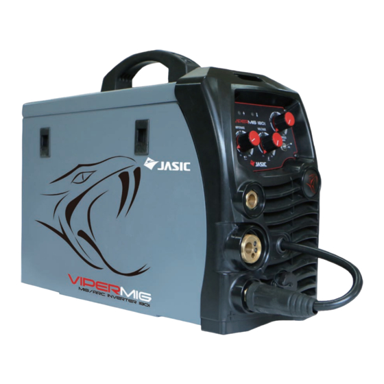
VIPER 180i MIG 180 Amp MIG -ARC Welder Welds: Steels, Stainless, Cast Iron, Bronze, Aluminum, Copper Features • Latest IGBT inverter technology • MIG with Gas and Gasless wire function • 11pound Spool compatible • IP21 S rating for environmental/safety protection •... -
Page 5: Safety - Cautions
SAFETY Welding and cutting equipment can be dangerous to both the operator and people in or near the surrounding working area, if the equipment is not correctly operated. Equipment must only be used under the strict and com- prehensive observance of all relevant safety regulations. Read and understand this instruction manual carefully before the installation and operation of this equipment. - Page 6 Fire hazard. Welding on closed containers, such as tanks,drums, or pipes, can cause them to explode. Flying sparks from the welding arc, hot work piece, and hot equipment can cause fires and burns. Ac- cidental contact of electrode to metal objects can cause sparks, explosion, overheating, or fire. Check and be sure the area is safe before doing any welding.
- Page 7 CAUTION 1. Working Environment. 1.1 The environment in which this welding equipment is installed must be free of grinding dust, corrosive chemicals, flammable gas or materials etc, and at no more than maximum of 80% humidity. 1.2 When using the machine outdoors protect the machine from direct sun light, rain water and snow etc; the temperature of working environment should be maintained within -10°C to +40°C.
-
Page 8: Machine Layout Pictogram
FRONT PANEL LAYOUT 1. Mains Power LED 2. Thermal Overload LED 3. Wire Feed Adjustment Knob (MIG/ MAG) 4. Voltage Adjustment Knob (MIG/MAG) 5. MIG/ARC Selector Switch ---5 6. Amperage Adjustment Knob (ARC) 7. "-" Output terminal 8. Euro Mig Torch Connector (MIG/MAG) 9. -
Page 9: Installation & Operation For Arc(Stick) Welding
Installation set up for ARC (Stick) Welding with VIPER 180 MIG -ARC (1) Turn the power source on and select the ARC function with the MIG/ ARC selector switch. (2) Connection of Output Cables Two sockets are available on this welding machine. For ARC welding the electrode holder is shown be connected to the negative socket, while the earth lead ( work piece ) is connected to the positive socket, this is known as DC- polarity. -
Page 10: Arc (Stick) Welding Information
ARC (Manual Metal Arc) Welding One of the most common types of arc welding is manual metal arc welding or stick welding. An electric current is used to strike an arc between the base material and a consumable electrode rod or ‘stick’ . The electrode rod is made of a material that is compatible with the base material being welded and is covered with a flux that gives off gaseous vapors that serve as a shielding gas and providing a layer of slag, both of which protect the weld area from atmospheric contamination. - Page 11 ARC (Stick) Welding Fundamentals Electrode Selection As a general rule, the selection of an electrode is straight forward,in that it is only a matter of selecting an elec- trode of similar composition to the parent metal. However, for some metals there is a choice of several electrodes, each of which has particular properties to suit specific classes of work.
-
Page 12: Installation & Operation For Mig Welding With Gas
(3) Put Power lead (Dongle) in the Positive (+) connection *Ensure that your spool gun selector is on "Standard"... - Page 13 Continued set up for MIG with Gas for VIPER 180 MIG ARC ( 9 ) Align the wire into the groove of the drive roller and close down the top roller making sure the wire is in the groove of the bottom drive roller, lock the pressure arm into place. (1 O) Apply a medium amount of pressure to the drive roller.
-
Page 14: Wire Feed Drive Roller Selection
Wire Feed Roller Selection The importance of smooth consistent wire feeding during MIG welding cannot be emphasized enough. Simply put the smoother the wire feed then the better the welding will be. Feed rollers or drive rollers are used to feed the wire mechanically along the length of the welding gun. Feed rollers are designed to be used for certain types of welding wire and they have different types of grooves ma- chined in them to accommodate the different types of wire. -
Page 15: Wire Installation Set Up Guide
Wire Installation and Set Up Guide Again the importance of smooth consistent wire feeding during MIG welding cannot be emphasized enough. The correct installation of the wire spool and the wire into the wire feed unit is critical to achieving an even and consistent wire feed. -
Page 16: Installation & Operation For Mig Welding With No Gas
Installation set up for MIG with Gasless wire for VIPER 180 MIG ARC (1) Select the MIG function with the ARC/MIG selector switch. (2) Connect the weld power cable to the Negative socket and tighten it. (3) Connect the earth cable plug into the Positive socket and tighten it. (4) Plug the welding torch into the Euro Mig torch connection socket on the front panel, and tighten it. - Page 17 Continued set up for MIG with Gasless wire for VIPER 180 MIG ARC ( 8 ) Carefully feed the wire over the drive roller into the outlet guide tube, feed through about 150mm into Align the wire into the groove of the drive roller and close down the top roller making sure the wire is in the groove of the bottom drive roller, lock the pressure arm into place.
-
Page 18: Installation Guide For Mig Torch Liner Installation
Mig Torch Liner Installation (1) Lay the torch out straight on the ground and remove the front end parts (2) Remove the liner retaining nut. (3) Carefully pull the liner out of the torch cable assembly (4) Select the correct new liner and carefully unravel avoiding putting any kinks in the liner, if you kink the liner it will make it no good and will require replacement. -
Page 19: Mig Torch And Wire Feeder Set Up Guide For Aluminum Mig Wire
Torch & Wire Feed Set Up for Aluminum Wire (1) Lay the torch out straight on the ground and remove the front end parts (2) Remove the liner retaining nut. (3) Carefully pull the liner out of the torch cable assembly (4) Select a PA or Teflon liner and carefully unravel it without kinking it. - Page 20 Continued Torch & Wire Feed Set Up for Aluminum Wire (1 O) Fit and tighten the torch euro connection to the machine euro connector (11) Install a U groove drive roller of the correct size for the diameter wire being used. (12) Place aluminum wire onto spool holder.
-
Page 21: Spoolgun Installation And Operation
Installation set up of the Spool Gun for Vipermig 180i Select Spool Gun using the Standard/Spool Gun selector switch.(Lift machine side panel cover) Connect the Spool Gun to the Euro MIG torch connection socket on the front panel, and tighten it. - Page 22 Continued set up of the Spool Gun with Viper 180i Carefully feed the wire over the drive roller into the outlet guide tube, feed through into the torch neck. Check that the drive roller being used complies with the wire diameter, replace the roller if necessary. (10) Align the wire into the groove of the drive roller and release the tension arm making sure the wire is in the groove of the drive roller.
-
Page 23: Mig (Metal Inert Gas) Welding
MIG (Metal Inert Gas) Welding Definition of MIG Welding - MIG (metal inert gas) welding also known as GMAW (gas metal arc welding) or MAG (metal active gas welding), is a semi-automatic or automatic arc welding process in which a continu ous and consumable wire electrode and a shielding gas are fed through a welding gun. - Page 24 Gas) MIG (Metal Inert Welding Short Circuit Transfer - Short circuit transfer is the most common used method whereby the wire elec trode is fed continuously down the welding torch through to and exiting the contact tip. The wire touch es the work piece and causes a short circuit the wire heats up and begins to form a molten bead, the ·...
-
Page 25: Basic Mig Welding Guide
Basic MIG Welding. Good weld quality and weld profile depends on gun angle, direction of travel, electrode exten sion (stick out), travel speed, thickness of base metal, wire feed speed (amperage) and arc voltage. To follow are some basic guides to assist with your setup. Gun Position - Travel Direction, Work Angle Gun position or technique usually refers to how the wire is directed at the base metal, the angle and travel direction chosen. - Page 26 Travel Angle - Travel angle is the right to left angle relative to the direction of welding. A travel angle of 5°- 15° is ideal and produces a good level of control over the weld pool. A travel angle greater that 20° will give an unstable arc condition with poor weld metal transfer, less penetration, high levels of spatter, poor gas shield and poor quality finished weld.
- Page 27 Travel Speed - Travel speed is the rate that the gun is moved along the weld joint and is usually measured in mm per minute. Travel speeds can vary depending on conditions and the welders skill and is limited to the welders ability to control the weld pool. Push technique allows faster travel speeds than Drag technique.
- Page 28 Wire types and sizes - Use the correct wire type for the base metal being welded. Use stainless steel wire for stainless steel, aluminum wires for aluminum and steel wires for steel. Use a smaller diameter wire for thin base metals. For thicker materials use a larger wire diameter and larger machine, check the recommended welding capability of you machine.
-
Page 29: Sb15 And Twc 2 Torch Parts
SB15 MIG TORCH 180A AIR COOLED MIG WELDING TORCH Rating:180A CO² 150A mixed gas EN60974-7 @ 60% duty cycle. 0.6 to 1.0mm wires SB15 PARTS Air Cooled MIG Torch 180A CO , 150A Mixed Gas @ 60% Duty Cycle COMPONENTS: PART NO. - Page 30 JASIC Technologies America Inc 25503 74th Ave S Kent WA 98032 USA VIPERMIG Phone: +1 253-859-6277 / +1 253-859-6278 FAX: +1 253-859-6286 EMAIL: sales@razorweld.com Spare Parts for Tweco 2 style torches Torch Model Description Part Number EAN CODE 15 FT Welding Torch Classic Style...
-
Page 31: Mig Welding Shooting Guide
MIG WELDING TROUBLE SHOOTING The following chart addresses some of the common problems of MIG welding. In all cases of equipment malfunction, the manufacturer’s recommendations should be strictly adhered to and followed. 1: Excessive Spatter Possible Reason Suggested Remedy Wire feed speed set too high Select lower wire feed speed Voltage too high Select a lower voltage setting... - Page 32 MIG WIRE FEED TROUBLE SHOOTING The following chart addresses some of the common WIRE FEED problems during MIG welding. In all cases of equipment malfunction, the manufacturer’s recommendations should be strictly adhered to and followed. 1: No wire feed Possible Reason Suggested Remedy Wrong mode selected Check that the ARC/MIG selector switch set to MIG position...
-
Page 33: Arc Welding Trouble Shooting Guide
ARC (Stick) WELDING TROUBLE SHOOTING The following chart addresses some of the common problems of ARC welding. In all cases of equipment malfunction, the manufacturer’s recommendations should be strictly adhered to and followed. 1: No arc Possible Reason Suggested Remedy Incomplete welding circuit Check earth lead is connected. - Page 34 We recommend that you close the cylinder valve when the machine is not in use. JASIC TECHNOLOGIES AMERICA INC, authorised representatives or agents of JASIC TECHNOLOGIES AMERICA INC will not be liable or responsible for the loss of any gas.
-
Page 35: Warranty And Conditions
WARRANTY JASIC Technologies America Inc (‘Us’ , ‘We’) warrants that the following products under VIPERMIG supplied by Us and purchased by you from an Authorised VIPERMIG Dealer throughout the U.S.A & Canada are free of Material and Faulty Workmanship defects except for those products listed under ‘Warranty Exclusions’... - Page 36 VIPERMIG JASIC Technologies Americ a Inc 25503 74th Ave S, Kent Washington, 98032 Ph : 253-859-6277, 253-859-6278 Fax : 253-859-6286 e-mail: sales@razorweld.com...
- Page 37 180i...
- Page 39 Installation set up of the Spool Gun for Select Spool Gun using the Standard/Spool Gun selector switch. Connect the Spool Gun to the Euro MIG torch connection socket on the front panel, and tighten it. Connect the Spool Gun control cable to the receptacle and tighten it. When connecting the torch be sure to tighten the connection.
- Page 40 Continued set up of the Spool Gun with Carefully feed the wire over the drive roller into the outlet guide tube, feed through into the torch neck. Check that the drive roller being used complies with the wire diameter, replace the roller if necessary. Align the wire into the groove of the drive roller and release the tension arm making sure the wire is in the groove of the drive roller.
Need help?
Do you have a question about the VIPERMIG 180i and is the answer not in the manual?
Questions and answers