Table of Contents
Advertisement
Quick Links
Advertisement
Table of Contents

Related Manuals for J-Tech Digital JTECH-VW-4KPR


Summary of Contents for J-Tech Digital JTECH-VW-4KPR
- Page 1 4K HDMI+USB KVM Extender over IP / Fiber With POE Operation Instructions...
-
Page 2: Table Of Contents
Table of Contents Introduction…………………………………………………………………...3 Features………………………………………………………………………3 Package Contents……………………………………………………..…….3 Specifications………………………………………………………………...4 Hardware Description…………………………………………….…………5 5.1 Transmitter……………………………………………………………..…..5 5.2 Receiver………………………………………………………………..…..6 5.3 Descriptions Buttons…………………………………………………..…..7 Installation…………………………………………………………………...11 6.1 Device Connection……………………………………………………….11 6.2 IP Configuration………………………………………………………..…14 Web User Interface Configuration………………………………………..17 7.1 System…………………………………………………………………….17 7.1.1 Version Information……………………………………………17 7.1.2 Update Firmware………………………………………………18 7.1.3 Utilities…………………………………………………………..19 7.1.4 Statistics………………………………………………………...20 7.2 Video Wall…………………………………………………………………21 7.2.1 Basic Setup……………………………………………………..21... -
Page 3: Introduction
1. INTRODUCTION The 4K HDMI & USB over IP Extender is a solution for audio, video and USB signal extension via Local Area Network (LAN). It can be used as audio, video and KVM extender over IP and applied to point to point, point to multi-point, multi-point to multi-point and screen wall broadcast system controlled by USB, RS232, IR and configured the 4K HDMI &... -
Page 4: Specifications
4. SPECIFICATION Performance Protocol TCP, UDP, RTSP, RTP, DHCP, IGMP, Multicast, IPV4 Support Video format 4K@30HZ, 1080P/1080i/720P/576P/576i/480P/480i Support Audio format Stereo 192Kbps HDCP Compliant IR Frequency 38 -56 KHZ RS232 Baud rate Default 115200bps, total 8 kinds optional IP setting &Group ID setting Default IP Automatic allocation Group ID... -
Page 5: Hardware Description
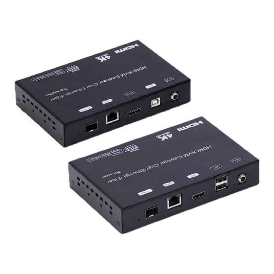
5. HARDWARE DESCRIPTION 5.1 Transmitter 1) Power input port 2) Power input indicator 3) USB 4) HDMI input 5) Ethernet port 6) Fiber Out 7) Indicator of status 8) IR-RX port 9) IR-TX port 10) RS232 port 11) Normal: For serial over IP; Program: For serial control or getting the debug information 12) 4 bit Dip switch 13) Group Switch... -
Page 6: Receiver
5.2 Receiver 1) Power input port 2) Power input indicator 3) USB 4) HDMI output 5) Ethernet port 6) Fiber In 7) Indicator of status 8) IR-RX port 9) IR-TX port 10) RS232 port 11) Normal: For serial over IP; Program: For serial control or getting the debug information 12) 4 bit Dip switch 13) Group Switch... -
Page 7: Descriptions Buttons
5.3 Descriptions Buttons: (Host: Transmitter; Client: Receiver) Button State for Unicast Mode: HDMI Extender: Default Mode will be highlighted in GREEN * Item will be described in Descriptions Unicast Digital Button State Transmitter Receiver Button One : Button Two : Button One : Button Two : Short Press... - Page 8 Descriptions: Feature /Button Feature Descriptions Remote/Loopback When System is all setup, short press this button will change between remote / local loopback Snoop (on/off) When System is all setup and video is displayed at the client side. Long Press this button will for the local loop back port to be enabled for Snooping feature.
- Page 9 Buttons that shall not be removed for this setup: Depending on customer feature needs. Example: If customer have loopback feature, than button one is required. Button State for Multicast Mode: HDMI Extender: Default Mode will be highlighted in GREEN * Item will be described in Descriptions Multicast Digital Button State Transmitter...
- Page 10 Descriptions: Feature /Button Feature Descriptions Remote/Loopback When System is all setup, short press this button will change between remote / local loopback Snoop (on/off) When System is all setup and video is displayed at the client side. Long Press this button will for the local loop back port to be enabled for Snooping feature.
-
Page 11: Installation
6. INSTALLATION 6.1 Device Connection 1. Check the power supply is unplugged. 2. Set up the group of the transmitter with the correspondent receiver for signal extension and display. 3. Connect the Transmitter to video source with HDMI cable, and connect Receiver to a monitor or display with HDMI cable. - Page 12 ◆ Application Pattern ■ Unicast ■ Multicast a. Video Distribution...
- Page 13 b. Matrix Distribution c. Billboard & Kiosk, PC to HDMI and USB Interactive Monitor...
-
Page 14: Ip Configuration
■ Screen Wall 6.2 IP Configuration The 4K HDMI & USB Over IP Extender can configure via LAN in the same subnet. 1. Assign a LAN IP address to the computer in the same subnet. The IP address default of the Transmitter and Receiver is B class Networking: 169.254.xxx.xxx. - Page 15 2. Connect the TX and RX with the Ethernet switch, Then connect the PC with the Ethernet switch. Because this unit support DHCP, Different unit with different IP address of the factory reset, so The first thing we need know the IP address of each unit. There is two way to get the IP address 1) Via “Node List”...
- Page 16 2) The second way. Connect all devices with proper cables except video source, please refer to Figure 2 Figure 2. Demonstrate the 4K HDMI & USB Over IP Extender 3) After activation, the device information including the Transmitter and Receiver IP address will be shown in the lower right corner. Remember the Transmitter and Receiver IP address on monitor screen and then plug HDMI video source cable into Transmitter.
-
Page 17: Web User Interface Configuration
3. The administrator can input Transmitter or Receiver IP address into address bar of web browser (Recommend the Google Chrome) to enter the Extender Web UI. If link success, administrator will see the Web UI as shown in Figure 4. ... -
Page 18: Update Firmware
7.1.2 [Update Firmware] To update the firmware of the connected extender, please click on the [Select File] to select the firmware and click on [Upload] to upload the firmware and update accordingly. Transmitter Firmware Update: please select [webfw.bin] to update ... -
Page 19: Utilities
7.1.3 [Utilities] There are some functions Factory Default: Click on to return to the factory default when necessary Reboot: Click on to reboot the extender system Console API Command: Input Linux command for advanced setting... -
Page 20: Statistics
7.1.4 [Statistics] Indicating the extender linking and working status... -
Page 21: Video Wall
7.2 Video Wall To set up the video wall application 7.2.1 [Basic Setup] Bezel and Gap Compensation: Dimension of the screen (inside and outside width and height) OW: outside width OH: outside height VW: viewable width VH: viewable height Please NOTE: 1) The viewable width must be less than the outside width, and the viewable height must be less than the outside height. - Page 22 Wall Size and Position Layout: Select number of vertical and/ or horizontal monitors, row position and column position. Vertical monitor number 1~8, horizontal monitor number 1~16...
- Page 23 Preferences: Select the video fit in the screen or stretch out and the rotate angle...
- Page 24 Apply To: 1) All: Configure all Transmitter and Receiver in the same Group IP. 2) This (Local): The IP you input into address bar of web browser. 3) Hosts or Clients: select which Transmitter or Receiver you want to configure.
-
Page 25: Advanced Setup
7.2.2 [Advance Setup]... - Page 26 Before enter “Advanced Setup”, please complete the “Basic Setup” as follows: Step1: In “Basic Setup”, select Vertical and Horizontal Monitor Count. For example Vertical Monitor Count = 3, Horizontal Monitor Count = 5 Sept2: In “Advanced Setup”, choose the target of the video wall to control...
- Page 27 If user make incorrect operations, press “Reset” in Reset to Basic Setup function. Setup the video output to “Fit In’ or “Stretch Out” mode in the screen Setup the rotation angle of the video output Set up the number of vertical and horizontal monitor based on the video wall layout.
- Page 28 Setup the column position of monitor, number from 0 to the total number of horizontal monitor. Setup the video position shift and video enlarge. Horizontal Shift: Setup the video horizontal shift, Left or Right Vertical Shift: Setup the video vertical shift, Up or Down ...
-
Page 29: Network
Consol API Command: Input Linux command to do advanced setup. 7.3 Network: Update the network setup of the extender system 7.3.1 [IP Setup] Auto IP: use automatically Extender assign IP system for example: 169.254.xxx.xxx. -
Page 30: Casting Mode
DHCP: use the DHCP of the external device such as the IP sharer to assign IP. Static: use the static IP to assign manually. 7.3.2 [Casting Mode] Select the broadcast mode of the extender application Multicast: point to multiple points or multiple point to multiple points broadcast ... -
Page 31: Functions
7.4 Functions: Setup the video output and USB extension mode for Transmitter Setup the video output and USB extension mode for Receiver... -
Page 32: Ip Setup
7.4.1 [Video over IP]: Setup the video output mode Enable Video over IP: Check to enable video extension over IP Enable Video Wall: Check to enable the video extension for building up video wall Enable EDID Copy: This function is limited to copy one of the ... -
Page 33: Casting Mode
Customize Scalar Output Mode for Receiver Timeout for Detecting Video Lost 7.4.2 [USB over IP]: Setup the USB extension mode Enable USB over IP: Check to enable USB extension mode over IP Operation Mode: Including “auto select mode”, “active on line” and “active per request”... -
Page 34: Serial Over Ip
7.4.3 [Serial over IP]: set up the serial extension mode Select Type 2 as operation mode Set up the baud rate for Type 2. Serial Over IP Broadcast Mode Setting... -
Page 35: Broadcast Configuration Example
8. BROADCAST CONFIGURATION SETTING There are some examples to show the setup for unicast, multicast, matrix and video wall. Broadcast setting including unicast and multicast 8.1 Multicast: To enable the USB interactive devices controlled by turns, please check “Auto select USB operation mode per casting mode” 8.2 Unicast: 8.3 Matrix: Install multiple transmitters and setting ID of these transmitters individually,... -
Page 36: Video Wall
8.4 Video wall: A 3X5 (row x column) video wall setting example here for reference. In multicast and matrix application mode, access the Web user interface of correspondent receiver to setup. 8.4.1 (Basic Setup) Please refer to “Section 6.2.1 Basic setup” and follow the steps as below. Step1: Set up the vertical monitor count to “3”... -
Page 37: Advanced Setup
8.4.2 Advanced Setup Select the monitor you want to control. The one you select will show “This” in green in video wall matrix layout. Take below diagram for example, the monitor we select to control here is the monitor in the upper left corner. Example for the video wall control Here’s the diagram of the actual video wall layout showing the selected monitor in the upper left corner with green outline. - Page 38 Returned to the previous setup of video wall quickly when incorrect operation was input Reset Adjust the horizontal position of the video output, “Left/Right Shift”, the selected monitor to adjust is shown with green outline. Adjust the vertical position of the video output, “Up/Down Shift”, the selected monitor to adjust is shown with green outline.
- Page 39 Horizontal Scale Up: To scale up the video output horizontally as the monitor shown with green outline Vertical Scale Up: To scale up the video output vertically as the monitor shown with green outline...
-
Page 40: Warranty
WARRANTY If your product does not work properly because of a defect in materials or workmanship, our Company (referred to as "the warrantor" ) will, for the length of the period indicated as below, (Parts(2)Year, Labor(90) Days) which starts with the date of original purchase ("Limited Warranty period"), at its option either(a) repair your product with new or refurbished parts, or (b) replace it with a new of a refurbished product.
Need help?
Do you have a question about the JTECH-VW-4KPR and is the answer not in the manual?
Questions and answers