Table of Contents
Advertisement
Available languages
Available languages
Quick Links
Installation Guide
For Models:
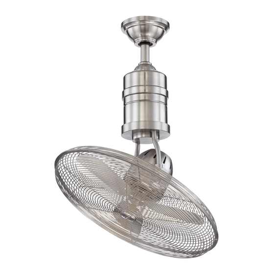
BW321AG3
BW321SS3
3170356
net weight of fan: 15.63 lb (7.09 kg)
READ THESE INSTRUCTIONS AND
SAVE THEM FOR FUTURE USE
Table of Contents:
Safety Tips. pg. 1
Unpacking Your Fan. pg. 2
Parts Inventory. pg. 2
Installation Preparation. pg. 3
Hanging Bracket Installation. pg. 3
Fan Assembly. pgs. 4 - 5
Wiring. pgs. 5 - 6
Canopy Assembly. pg. 6
Wall Control Operation. pg. 7
Remote Control Operation. pg. 8
Testing Your Fan. pg. 8
Troubleshooting. pg. 9
Warranty. pg. 9
Parts Replacement. pg. 9
PRINTED IN CHINA
Advertisement
Chapters
Table of Contents

Related Manuals for Craftmade BW321SS3


Summary of Contents for Craftmade BW321SS3
-
Page 1: Table Of Contents
READ THESE INSTRUCTIONS AND SAVE THEM FOR FUTURE USE Installation Guide For Models: BW321AG3 Table of Contents: BW321SS3 Safety Tips. pg. 1 Unpacking Your Fan. pg. 2 Parts Inventory. pg. 2 Installation Preparation. pg. 3 Hanging Bracket Installation. pg. 3 Fan Assembly. -
Page 2: Safety Tips
SAFETY TIPS. WARNING: To reduce the risk of electrical shock, turn off the electricity to the fan at the main fuse box or circuit panel before you begin the fan installation or before servicing the fan or installing accessories. READ ALL INSTRUCTIONS AND SAFETY INFORMATION CAREFULLY BEFORE INSTALLING YOUR FAN AND SAVE THESE INSTRUCTIONS. -
Page 3: Unpacking Your Fan
1. Unpacking Your Fan. Carefully open the packaging. Remove items from Styrofoam inserts. Remove motor assembly and place on carpet or Styrofoam to avoid damage to finish. Do not discard fan carton or Styrofoam inserts should this fan need to be returned for repairs. -
Page 4: Installation Preparation
3. Installation Preparation. blade edge To prevent personal injury and damage, ensure that the hanging location of the fan allows the fan cage a inches 10 feet clearance of 10 feet (3.05m) from the floor and that (3.05m) (76cm) the edges of the fan cage will be at least 30in. (76 cm) from any wall or obstruction. -
Page 5: Fan Assembly. Pgs
5. Fan Assembly. If you wish to extend the hanging length of set screw set screw hole your fan, you must remove the hanging ball stop pin from the 4½in. downrod provided to use with an extended downrod (sold separately). [If you wish to use the 4½in. -
Page 6: Wiring. Pgs
5. Fan Assembly. (cont.) safety cable loop wood With the hanging bracket secured to the outlet box ceiling and able to support the fan, you are now ready to joist hang your fan. Grab the fan firmly with two hands. wood screw Slide downrod through opening in hanging bracket and washer... -
Page 7: Canopy Assembly
6. Wiring. (cont.) IN ORDER TO WIRE WALL CONTROL, remove outlet box wall existing wall switch. Wire the WALL CONTROL control with wire connectors provided as shown in plate diagram at right. * Wrap each wire connector separately with green/ green/ green/ bare... -
Page 8: Automated Learning Process/Activating Code
8. Automated Learning Process./ code Activating Code. switches CAUTION: The remote control transmitter can be TRANSMITTER programmed to multiple receivers or fans. If this is (back) not desired, turn wall switch off to any other programmable receiver or fan. Remove battery cover from back side of remote control transmitter. -
Page 9: Remote Control Operation
10. Remote Control Operation. HI button - turns lower fan to HIGH speed main MED button - turns lower fan to MEDIUM speed LOW button - turns lower fan to LOW speed OFF button - turns lower fan OFF button - turns main fan ON/OFF when pressed once (i.e., controls ROTATION of the ENTIRE fan) lower fan... -
Page 10: Troubleshooting
2. Check to be sure code switches in remote to arrange for return of fan. Return fan, shipping prepaid, to control transmitter and wall control are set Craftmade/Ellington. We will repair or ship you a replacement fan, and we will pay the return shipping cost. properly. - Page 11 GUARDARLAS PARA UTILIZACION FUTURA Guía de instalación Para modelos: BW321AG3 Indice de materias: BW321SS3 Sugerencias de seguridad. Pág. 1 Desempaquetado del ventilador. Pág. 2 Inventario de piezas. Pág. 2 Preparación para la instalación. Pág. 3 Instalación del soporte de montaje. Pág. 3 Ensamblaje del ventilador.
-
Page 12: Sugerencias De Seguridad. Pág
SUGERENCIAS DE SEGURIDAD. ADVERTENCIA: Para evitar la posibilidad de una descarga eléctrica, desconectar la corriente en la caja de fusibles principal o el interruptor protector antes de iniciar la instalación del ventilador o antes de repararlo o instalar accesorios. LEER TODAS LAS INSTRUCCIONES E INFORMACIÓN DE SEGURIDAD CUIDADOSAMENTE ANTES DE INSTALAR SU VENTILADOR Y GUARDAR ESTAS INSTRUCCIONES. -
Page 13: Desempaquetado Del Ventilador. Pág
1. Desempaquetado del ventilador. Abrir el empaque cuidadosamente. Sacar los artículos del embalaje. Sacar la unidad del motor y ponerla en una alfombra o en el embalaje para evitar rayar el acabado. Guardar la caja de cartón o el empaquetamiento original en caso de que tenga que mandar el ventilador para alguna reparación. -
Page 14: Preparación Para La Instalación. Pág
3. Preparación para la instalación. Para prevenir daño corporal y otros daños, estar borde del aspa seguro de que el lugar en donde va a colgar el 76cm ventilador le permite un espacio libre de 3,05m (10 pies) entre la caja protectora del ventilador y el 3,05m pulg.) piso y 76cm (30 pulg.) entre el borde de la caja... -
Page 15: Ensamblaje Del Ventilador. Págs
5. Ensamblaje del ventilador. agujero para Si usted desea extender la longitud colgante del el tornillo tornillo ventilador, usted tendrá que quitar la bola que sirve para perno de fijación de fijación colgar del tubo de 11,43cm provisto para usarla con un de tope tubo más largo (a la venta por separado). -
Page 16: Instalación Eléctrica. Págs
viga de 5. Ensamblaje del ventilador. (cont.) madera bucle del cable Ya que esté sujetado el soporte de montaje a la caja de salida y de seguridad capaz de apoyar el ventilador, usted está listo para colgar el ventilador. Agarrar el ventilador firmemente con las dos manos. Deslizar el tubo por la abertura del soporte de montaje y dejar que se detenga la bola en el soporte de montaje. -
Page 17: Colocación De La Cubierta Decorativa. Pág
6. Instalación eléctrica. (cont.) PARA HACER LA INSTALACION ELECTRICA DEL caja de control CONTROL DE PARED, quitar el interruptor de pared salida de pared existente. Alambrar el CONTROL DE PARED con los placa conectores para cable provistos así como se muestra en el diagrama al lado. -
Page 18: Proceso De Aprendizaje Automático./ El Activar El Código
8. Proceso de aprendizaje automático./ El activar el código. conmutadores de bolígrafo los códigos PRECAUCION: Se puede programar el transmisor del control remoto para usar con varios receptores o TRANSMISOR (parte de atrás) ventiladores. Si no desea hacer esto, apagar el interruptor de cualquier otro receptor o ventilador programable. -
Page 19: Funcionamiento Del Control Remoto. Pág
10. Funcionamiento del control remoto. Botón HI - pone el ventilador inferior en velocidad ALTA Botón MED - pone el ventilador inferior en velocidad MEDIA ventilador principal Botón LOW - pone el ventilador inferior en velocidad BAJA Botón OFF - APAGA el ventilador inferior Botón - ENCIENDE/APAGA el ventilador principal cuando se oprime el botón una vez (es decir, controla la... - Page 20 5. Verificar la instalación eléctrica del ventilador. Craftmade/Ellington pagará los gastos de envío de regreso. 6. Averiguar que la luz roja se prende en el GARANTIA LIMITADA DE 6 AÑOS hasta DE POR VIDA: transmisor del control remoto cuando se oprima CRAFTMADE/ELLINGTON reparará...
Need help?
Do you have a question about the BW321SS3 and is the answer not in the manual?
Questions and answers