Advertisement
Table of Contents
Specifications
Power Requirement .....................................110V
Air Pressure Requirement ........................ 90 PSI
Speed ................................................. 3000 RPM
Torque ...................................................135 ft/lbs
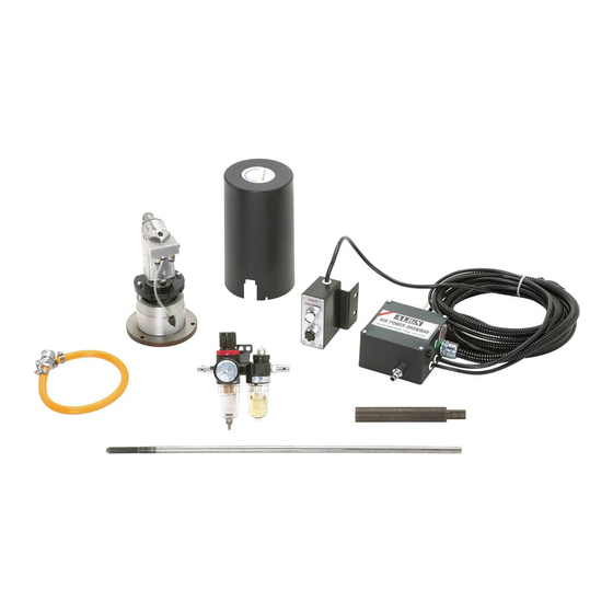
Inventory
Refer to Figure 1 and the table below to inventory
the contents of the shipping box.
REF PART #
DESCRIPTION
1
PH8369001
PNEUMATIC MOTOR
2
PH8369002
MOTOR COVER
3
PH8369003
CONTROL ASSEMBLY
4
PH8369004
AIR HOSE W/CONNECTORS
5
PH8369005
AIR REGULATOR/FILTER/LUBRICATOR
6
PH8369006
DRAWBAR BOLT HEAD
7
PH8369007
DRAWBAR SHAFT 7/16-20 X 22
8
PH8369008
COMPLETE BOLT BAG
Bolt Bag Contents
Phillips Head Screws M4.7 x 10 ....................... 3
Cap Screws M6-1 x 10 ...................................... 2
Cap Screws M6-1 x 15 ...................................... 4
Cap Screws M6-1 x 20 ...................................... 3
Lock Washers 6mm ........................................... 3
Flat Washers 6mm ............................................ 2
WARNING: NO PORTION OF THIS MANUAL MAY BE REPRODUCED IN ANY SHAPE
OR FORM WITHOUT THE WRITTEN APPROVAL OF GRIZZLY INDUSTRIAL, INC.
Qty
COPYRIGHT © MARCH, 2008 BY GRIZZLY INDUSTRIAL, INC.
#TS10501 PRINTED IN TAIWAN
MODEL H8369
PNEUMATIC POWER
DRAWBAR
INSTRUCTIONS
�
�
Figure 1. Model H8369 inventory.
If any nonproprietary parts are missing (e.g. a
nut or a washer), we will gladly replace them; or
for the sake of expediency, replacements can be
obtained at your local hardware store.
If you need help with your new pneumatic power
drawbar, call our Tech Support at: (570) 546-
9663.
�
�
�
�
�
�
Advertisement
Table of Contents

Related Manuals for Grizzly H8369


Summary of Contents for Grizzly H8369
-
Page 1: Specifications
Flat Washers 6mm ... 2 COPYRIGHT © MARCH, 2008 BY GRIZZLY INDUSTRIAL, INC. WARNING: NO PORTION OF THIS MANUAL MAY BE REPRODUCED IN ANY SHAPE OR FORM WITHOUT THE WRITTEN APPROVAL OF GRIZZLY INDUSTRIAL, INC. MODEL H8369 PNEUMATIC POWER INSTRUCTIONS �... -
Page 2: Drawbar Assembly
Figure 5. Calculating the length of the new shaft. Remove the necessary amount, if any, from the top of the new drawbar shaft to make the total length of the shaft equal to the total length calculated in Step 2. H8369 Pneumatic Power Drawbar ���� ��� ⁄ "... - Page 3 ���������� Figure 7. Measuring the amount of the new drawbar head bolt to remove. H8369 Pneumatic Power Drawbar Center drill and drill the bottom of the new bolt head to provide a tight, press-fit 1 deep hole for the new drawbar shaft.
-
Page 4: Installation
(see Figure 6). Pneumatic Control Box Hose 2 Figure 6. Example of the air regulator unit connected to the pneumatic control box. H8369 Pneumatic Power Drawbar Included Air Hose Air Regulator Unit BURSTING HAZARD! Never exceed the maxi-... -
Page 5: Operation
90–120 PSI. 11. Pull the air pressure adjustment knob up, then turn it until the pressure gauge reads 90 PSI. H8369 Pneumatic Power Drawbar Operation Connect the drawbar unit to power. Cutting tools are sharp! When using the power drawbar, the tooling will spin. - Page 6 ��� ������ ��� ���� ���� ������� ����� ��� ������� ����� ��� �������� ��� ������� � ������ �������� � ������ ������� ������ �� ����� � ������ �������� ������ ��� ���� ���� ����� ��� � � �������� ������ ��� � ����� ������ �...
Need help?
Do you have a question about the H8369 and is the answer not in the manual?
Questions and answers