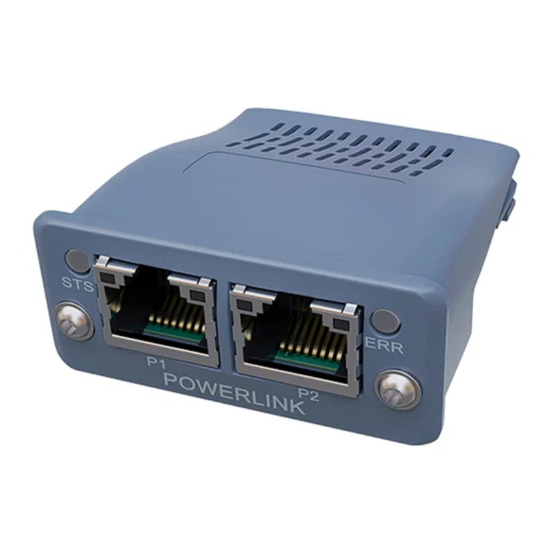
HMS Networks Anybus CompactCom 40 POWERLINK Application Note
Hide thumbs
Also See for Anybus CompactCom 40 POWERLINK:
- Network manual (185 pages) ,
- Network manual (259 pages)
Summary of Contents for HMS Networks Anybus CompactCom 40 POWERLINK
- Page 1 ENGLISH ® ™ Anybus CompactCom 40 - POWERLINK APPLICATION NOTE - DNA CONFIGURATION USING AUTOMATION STUDIO SCM-1202-206 Version 1.1 Publication date 2022-06-03...
- Page 2 HMS Networks reserves the right to modify its products in line with its policy of continuous product development. The information in this document shall therefore not be construed as a commitment on the part of HMS Networks and is subject to change without notice.
-
Page 3: Table Of Contents
® ™ Anybus CompactCom 40 - POWERLINK Table of Contents 1. Preface ..........................1 1.1. About this Document ......................1 1.2. Document History ......................1 2. Overview ..........................2 2.1. Line Topology ........................2 2.2. Star Topology ........................3 3. Configuration .......................... 4 3.1. - Page 4 This page is intentionally left blank.
-
Page 5: Preface
Anybus CompactCom 40 - POWERLINK 1. Preface 1.1. About this Document This document describes how to setup Dynamic Node Allocation (DNA) in B&R Automation Studio with the Anybus CompactCom 40 POWERLINK. 1.2. Document History Version History Date 1.00 Initial version 2021-11-23 1.01... -
Page 6: Overview
DNA is supported by the Anybus CompactCom 40 POWERLINK from firmware version 1.17. NOTE To enable the DNA functionality in the Anybus CompactCom 40 POWERLINK, the value of the node number in the Network Configuration Object (Instance #1) must be set to 0. -
Page 7: Star Topology
® ™ Star Topology Anybus CompactCom 40 - POWERLINK 2.2. Star Topology A conventional HUB can be used to create a star-topology. However, since the ports of a conventional HUB cannot be controlled, node numbers for nodes connected directly to the HUB (head-of-line nodes) cannot be set with DNA. -
Page 8: Configuration
Add your PLC to the project. Make sure the PLC supports the DNA functionality. In this example, the B&R X20CP1684 PLC is used. Upload the XDD-file from the Anybus CompactCom 40 POWERLINK using the HMS POWERLINK XDD File Uploader. NOTE The file uploader requires the Anybus CompactCom 40 POWERLINK to have a node number not equal to 0. - Page 9 Managing Node = 240 Hub port on predecessor The port number of the predecessor the The port number of the predecessor the Anybus CompactCom Anybus CompactCom 40 POWERLINK is 40 POWERLINK is connected to. connected to. EPL_DNA_InPort The input hub port of the Anybus The input hub port of the Anybus CompactCom 40 CompactCom 40 POWERLINK.
- Page 10 This page is intentionally left blank.
- Page 11 This page is intentionally left blank.
- Page 12 This page is intentionally left blank.


Need help?
Do you have a question about the Anybus CompactCom 40 POWERLINK and is the answer not in the manual?
Questions and answers