Advertisement
Available languages
Available languages
Quick Links
If you have any questions regarding assembly or if parts are missing, DO NOT return this item to the
store where it was purchased. Please call our customer service number and have your instructions
and parts list ready to provide the model name, part name or factory number:
Pacific Standard Time: 8:30 a.m. - 4:30 p.m., Monday - Friday
Or visit our web site 24 hours a day, 7 days a week for product assistance at
THIS INSTRUCTION BOOKLET CONTAINS IMPORTANT SAFETY INFORMATION.
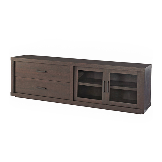
Steele TV Stand
Stock # BH46-084-899-02
# BH48-084-099-55
ADULT ASSEMBLY REQUIRED
www.whalenstyle.com
Or e-mail your request to parts@whalenfurniture.com
PLEASE READ AND KEEP FOR FUTURE REFERENCE.
Date 2019-01-24
866-942-5362
Rev. 0001-C
LOT NUMBER:
DATE PURCHASED: /
/
Advertisement

Subscribe to Our Youtube Channel
Related Manuals for Better Homes and Gardens BH48-084-099-55


Summary of Contents for Better Homes and Gardens BH48-084-099-55
- Page 1 DATE PURCHASED: / Steele TV Stand Stock # BH46-084-899-02 # BH48-084-099-55 ADULT ASSEMBLY REQUIRED If you have any questions regarding assembly or if parts are missing, DO NOT return this item to the store where it was purchased. Please call our customer service number and have your instructions...
- Page 2 M A X I M U M R E C O M M E N D E D W E I G H T L O A D S MANUFACTURER: Whalen Furniture Manufacturing CATALOG: Steele TV Stand MODEL # BH46-084-899-02/BH48-084-099-55 MADE IN MALAYSIA FITS UP TO MOST 80” FLAT PANEL TVs MAXIMUM LOAD 135 lb.
- Page 3 Important Before you begin: Open, identify and count all parts prior to assembly. Lay out parts on a flat and non- abrasive surface. You will need the parts identified on page 4 and 5 of this instruction manual. NOTE: IT IS VERY IMPORTANT TO USE GLUE WITH DOWELS. EXCESS GLUE CAN BE WIPED OFF WITH DAMP CLOTH.
- Page 4 Parts and Hardware List Please read completely through the instructions and verify that all listed parts and hardware are present before beginning assembly. A- Top Panel (Qty. 1) B- Bottom Panel (Qty. 1) C- Base Front Stretcher (Qty. 1) D- Base Back Stretcher (Qty. 1) E- Base Side Stretcher (Qty.
- Page 5 Parts and Hardware List Please read completely through the instructions and verify that all listed parts and hardware are present before beginning assembly. (1) Small Cam Lock (2) Large Cam Lock (3) Cam Bolt (Qty. 10+1 extra) (Qty. 12+1 extra) (Qty.
- Page 6 Drawer Assembling M6 x 30 mm Wood Dowel M4 x 38 mm Screw (4 used in this step) (4 used in this step) ④ ⑦ 1. Unpack the unit and confirm that you have all the hardware and required parts. Assemble the unit on a carpeted floor or the empty carton to avoid any scratch.
- Page 7 Drawer Assembling 4. Slide the Drawer Bottom Panel (R) into the grooves between the Drawer Side Panels (O and P) until fully inserted into the Drawer Back Panel (N).
- Page 8 Drawer Assembling M6 x 30 mm Wood Dowel (1 used in this step) ④ 5. Glue one M6 x 30 mm Wood Dowel (4) into the back center hole of the Drawer Bottom Support (Q) and attach it to the Drawer Back Panel (N).
- Page 9 Drawer Assembling Cam Bolt Small Cam Lock M6 x 30 mm Wood Dowel (5 used in this step) (5 used in this step) (6 used in this step) ③ ① ④ 6. Securely screw five Cam Bolts (3) into the designated small holes on the Drawer Front Panel (M) as shown.
- Page 10 Drawer Assembling M4 x 38 mm Screw (2 used in this step) ⑦ 8. Fasten the Drawer Back Panel (N) to the Drawer Bottom Support (Q) with two 38 mm Screws (7) using a Phillips screwdriver.
- Page 11 Drawer Assembling Handle Handle Bolt (1 used in this step) (2 used in this step) ⑭ 9. Attach one Drawer Handle (14) to the outside of Drawer Front (M) using two provided Handle Bolts (15). 10. Repeat the same procedure to assemble the other drawer.
- Page 12 Assembly Instructions Corner Connector (4 used in this step) M8 x 30 mm Wood Dowel (8 used in this step) ⑤ 15 mm Washer Head Screw (8 used in this step) ⑥ 11. Attach two Base Side Stretchers (E) between the Front and Back Stretchers (C and D) with eight Wood Dowels (5).
- Page 13 Assembly Instructions Floor Leveler (2 used in this step) ⑯ 13. Tightly screw two Floor Levelers (16) into the threaded inserts on the Base Front Stretcher (C) and set to the correct height.
- Page 14 Assembly Instructions C/D/E M8 x 30 mm Wood Dowel M4 x 50 mm Screw (10 used in this step) (12 used in this step) ⑤ ⑧ 14. Glue ten M8 x 30 mm Wood Dowel (5) into the inner holes of the Bottom Panel (B). 15.
- Page 15 Assembly Instructions Cam Bolt (6 used in this step) ③ 16. Securely screw the Cam Bolts (3) into the designated small holes on the Bottom Panel (B) using a Phillips screwdriver.
- Page 16 Assembly Instructions Cam Bolt M3 x 15 mm Pan Head Screw Magnetic Catch (6 used in this step) (4 used in this step) (2 used in this step) ③ ⑨ ⑩ 17. Securely screw six Cam Bolts (3) into the designated small holes on the Top Panel (A) using a Phillips screwdriver.
- Page 17 Assembly Instructions Large Cam Lock M10 x 40 mm Wood Dowel (12 used in this step) (12 used in this step) ② ⑰ 19. Glue twelve Wood Dowels (17) into the inner end holes of vertical panels (F, G and H) at both ends. 20.
- Page 18 Assembly Instructions 15 mm Washer Head Screw (40 used in this step) ⑥ 21. Now, go back and tighten all Cam Locks and Screws. Make sure that all the parts are tight and there are no gaps between the pieces. This will help keep the unit square. 22.
- Page 19 Assembly Instructions Shelf Pin Cam Lock Cover (4 used in this step) (4 used in this step) ⑫ ⑬ 23. Stand the unit upright. 24. Insert four Shelf Pins (12) into the holes at your desired height inside right compartment. Tilt and rest the Adjustable Shelf (K) onto the Shelf Pins (12).
- Page 20 Assembly Instructions Handle Handle Bolt (2 used in this step) (4 used in this step) ⑭ 26. Attach one Handle (14) to the front side of each Door (I and J) with the provided Handle Bolts (15). 27. Pick up Left Door (I) and attach the extended Hinge Arms to the Hinge Bases installed on the Partition Panel (G).
- Page 21 Assembly Instructions 30. Extend the Sliding Tracks on the Panels (F and G) all the way forward (including ball bearing cart). Then align the Slide Runners on the assembled drawers with the Slide Tracks and push the drawers carefully inside until it stops. NOTE: If the drawer does not go in smoothly, please take it out and repeat the step.
- Page 22 Assembly Instructions Tools required (not provided): Phillips screwdriver, stud finder, power drill and 1/8” drill bit. 31. Ask for assistance to position the assemble TV stand at the desired location against a wall. If necessary, adjust the installed Floor Levelers (18) at the bottom of the base to level the unit. Now, follow the instructions printed on the plastic bag containing the Tipping Restraint Hardware to attach the tip-over restraints to the unit and the wall.
-
Page 23: Care And Maintenance
Care and Maintenance Use a soft, clean cloth that will not scratch the surface when dusting. Use of furniture polish is not necessary. Should you choose to use polish, test first in an inconspicuous area. Using solvents of any kind on your furniture may damage your furniture’s finish. ... - Page 25 FECHA COMPRA: / Consola para Televisión Steele Serie # BH46-084-899-02 # BH48-084-099-55 ENSAMBLE REQUERIDO POR ADULTO Si tiene alguna pregunta acerca del ensamble o si alguna parte está faltante, no retorne esté producto a la tienda donde lo compró. Por favor llame a nuestro departamento de ayuda al cliente teniendo su instructivo y lista de partes para proveer el modelo, nombre de parte o el número de fábrica:...
- Page 26 M Á X I M A C A R G A R E C O M E N D A D A FABRICANTE: Whalen Furniture Manufacturing CATALOGO: Consola para Televisión Steele MODELO # BH46-084-899-02/BH48-084-099-55 HECHO EN MALASIA PARA LA MAYORIA DE TV’S DE 80”...
- Page 27 Importante Antes de comenzar: Abra, identifique y cuente todas las partes antes del ensamble. Coloque los componentes en una superficie plana y no abrasiva. Usted necesitará las partes identificadas en la página 4 y 5 de este manual de instrucciones. NOTA: Es muy importante utilizar pegamento con los pernos.
- Page 28 Lista de Partes y Artículos de Ferretería Por favor lea completamente las instrucciones y verifique que estén todas las partes antes de iniciar el ensamble. A- Panel superior (Cant. 1) B- Panel inferior (Cant. 1) C- Soporte frontal de base (Cant. 1) D- Soporte posterior de base E- Soporte lateral de base F- Panel izquierda lateral...
- Page 29 Lista de Partes y Artículos de Ferretería Por favor lea completamente las instrucciones y verifique que estén todas las partes antes de iniciar el ensamble. (1) Tuerca de fijación chica (2) Tuerca de fijación grande (3) Tornillo de fijación (Cant. 10+1 extra) (Cant.
- Page 30 Ensamble de cajón Perno M6 x 30 mm madera Tornillo M4 x 38 mm (4 usados en este paso) (4 usados en este paso) ④ ⑦ 1. Desempacar la unidad y confirmar que se tiene todo el herraje y partes requeridas. Ensamble la unidad sobre una área con alfombra o sobre el cartón para evitar daños a las piezas.
- Page 31 Ensamble de cajón 4. Deslice el panel inferior del cajón (R) en las ranuras entre los paneles laterales del cajón (O y P) hasta que esté completamente insertado en el respaldo del cajón (N).
- Page 32 Ensamble de cajón Perno M6 x 30 mm madera (1 usado en este paso) ④ 5. Pegar un perno M6 x 30 mm de madera (4) en el orificio central posterior del soporte inferior del cajón (Q) y adjuntarlo al respaldo del cajón (N).
- Page 33 Ensamble de cajón Tornillo de fijación Tuerca de fijación chica Perno M6 x 30 mm madera (5 usados en este paso) (5 usados en este paso) (6 usados en este paso) ③ ① ④ 6. Atornille cinco tornillos de fijación (3) en los orificios pequeños designados en el frente del cajón (M) como se muestra.
- Page 34 Ensamble de cajón Tornillo M4 x 38 mm (2 usados en este paso) ⑦ 8. Fijar el respaldo del cajón (N) en el soporte inferior del cajón (Q) con dos tornillos de 38 mm (7) con un desarmador estrella.
- Page 35 Ensamble de cajón Jaladera Tornillo para jaladera (1 usado en este paso) (2 usados en este paso) ⑭ 9. Adjuntar la jaladera (14) en la parte de afuera del frente de cajón (M) usando dos tornillos de jaladera (15) proveidos. 10.
- Page 36 Instructivo de ensamble Conector esquina (4 usados en este paso) Perno M8 x 30 mm madera (8 usados en este paso) ⑤ Tornillo de 15 mm especial (8 usados en este paso) ⑥ 11. Acople dos soportes laterales de la base (E) entre el soporte frontal de base y soporte posterior de base (C y D) con ocho pernos de madera (5).
- Page 37 Instructivo de ensamble Nivelador de piso (2 usados en este paso) ⑯ 13. Atornille dos niveladores de piso (16) en los inseros roscados en la soporte frontal de base (C) y fijar los a la altura correcta.
- Page 38 Instructivo de ensamble C/D/E Perno M8 x 30 mm madera Tornillo M4 x 50 mm (10 usados en este paso) (12 usados en este paso) ⑤ ⑧ 14. Pegar diez pernos M8 x 30 mm de madera (5) en los orificios interiores del panel inferior (B). 15.
- Page 39 Instructivo de ensamble Tornillo de fijación (6 usados en este paso) ③ 16. Atornille los tornillos de fijación (3) en los orificios pequeños designados en el panel inferior (B) con un desarmador estrella.
- Page 40 Instructivo de ensamble Tornillo de fijación Tornillo M3 x 15 mm cabeza redonda Magneto (6 usados en este paso) (4 usados en este paso step) (2 usados en este paso) ③ ⑨ ⑩ 17. Atornille seis tornillos de fijación (3) en los orificios pequeños designados en el panel superior (A) con un desarmador estrella.
- Page 41 Instructivo de ensamble Tuerca de fijación grande Perno M10 x 40 mm madera (12 usados en este paso) (12 usados en este paso) ② ⑰ 19. Pegar doce pernos de madera (17) en los orificios de extremo internas de los paneles verticales (F, G y H) en ambos extremos.
- Page 42 Instructivo de ensamble Tornillo de 15 mm especial (40 usados en este paso) ⑥ 21. Ahora, vuelve atrás y apriete todas los tuercas y tornillos de fijación. Asegúrese de que todas las partes estén apretados y que no haya espacios entre las piezas. Esto ayudará a mantener la unidad escuadra. 22.
- Page 43 Instructivo de ensamble Soporte de repisa Cubierta de tuerca (4 usados en este paso) (4 usados en este paso) ⑫ ⑬ 23. Poner la unidad en posición vertical. 24. Inserte cuatro soportes de repisa (12) en los orificios de la altura deseada en el interior del compartimiento de la derecha.
- Page 44 Instructivo de ensamble Jaladera Tornillo para jaladera (2 usados en este paso) (4 usados en este paso) ⑭ 26. Adjunte una jaladera (14) en el lado frontal de cada puerta (I y J) con los tornillos para jaladera (15). 27. Levante la puerta izquierda (I) y extienda los brazos de bisagra instalados en el panel de divisor (G). Aflojar el tornillo en la parte posterior de la base para un ajuste fácil.
- Page 45 Instructivo de ensamble 30. Extender las correderas en los paneles (F y G) completamente hacia adelante (incluyendo el carrito de baleros). Alinee las correderas sobre los cajones ensamblados con las correderas y empuje cuidadosamente los cajones en el interior hasta que se detenga. NOTA: Si el cajón no entra con problemas, por favor, eche un vistazo y repetir el paso.
- Page 46 Instructivo de ensamble Herramientas requeridas (no incluidas): Desarmador estrella, detector de vigas, taladro eléctrico y broca de 1/8”. 31. Pedir ayuda para colocar la consola para TV en la ubicación deseada contra una pared. Si es necesario, ajuste los niveladores de piso (18) instalados en la parte inferior de la base para nivelar la unidad. Ahora, siga las instrucciones impresas en la bolsa de plástico que contiene el juego de restricción de movimiento para fijar a la unidad y la pared.
-
Page 47: Mantenimiento Y Cuidados
Mantenimiento y cuidados Use una toalla suave y limpia para evitar daños y rayaduras. Uso de cera para pulir muebles no es necesario. Si desea usar cera revisar en una area que no sea visible para checar su funcionamiento. ...
Need help?
Do you have a question about the BH48-084-099-55 and is the answer not in the manual?
Questions and answers