Advertisement
Available languages
Available languages
Quick Links
If you have any questions regarding assembly or if parts are missing, DO NOT return this item to the
store where it was purchased. Please call our customer service number and have your instructions and
parts list ready to provide the model name, part name or factory number:
Or visit our web site 24 hours a day, 7 days a week for product assistance at
THIS INSTRUCTION BOOKLET CONTAINS IMPORTANT SAFETY INFORMATION.
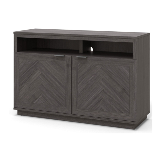
Hendrix TV Console
Stock # BH48-084-899-03
ADULT ASSEMBLY REQUIRED
Pacific Standard Time: 8:30 a.m. - 4:30 p.m., Monday - Friday
Or e-mail your request to parts@whalenfurniture.com
PLEASE READ AND KEEP FOR FUTURE REFERENCE.
Date 2021-06-23
BH48-084-899-04
BH48-084-899-05
866-942-5362
www.whalenstyle.com
Rev. 0001-A
LOT NUMBER:
DATE PURCHASED:
/
/
Advertisement

Related Manuals for Better Homes and Gardens Hendrix BH48-084-899-03


Summary of Contents for Better Homes and Gardens Hendrix BH48-084-899-03
- Page 1 LOT NUMBER: DATE PURCHASED: Hendrix TV Console Stock # BH48-084-899-03 BH48-084-899-04 BH48-084-899-05 ADULT ASSEMBLY REQUIRED If you have any questions regarding assembly or if parts are missing, DO NOT return this item to the store where it was purchased. Please call our customer service number and have your instructions and parts list ready to provide the model name, part name or factory number: 866-942-5362 Pacific Standard Time: 8:30 a.m.
- Page 2 G E N E R A L I N F O R M A T I O N , T I P S A N D T R I C K S 1. Please read the Assembly Instructions prior to assembling this product. 2.
- Page 3 IMPORTANT Before you begin: Open, identify and count all parts prior to assembly. Lay out parts on a flat and non-abrasive surface. You will need the parts identified on page 4 and 5 of this instruction manual. NOTE: IT IS VERY IMPORTANT TO USE GLUE WITH DOWELS. EXCESS GLUE CAN BE WIPED OFF WITH DAMP CLOTH.
- Page 4 Parts and Hardware List Please read completely through the instructions and verify that all listed parts and hardware are present before beginning assembly. A- Top Panel (Qty. 1) B- Fixed Shelf (Qty. 1) C- Left Side Panel (Qty. 1) D- Right Side Panel (Qty. 1) E- Lower Partition Panel (Qty.
- Page 5 Parts and Hardware List Please read completely through the instructions and verify that all listed parts and hardware are present before beginning assembly. (1) Cam Lock (2) Cam Bolt (3) M8 x 30 mm Wood Dowel (Qty. 32+1 extra) (Qty. 32+1 extra) (Qty.
- Page 6 Assembly Instructions ② x 30 NOTE: Please do not fully tighten all bolts/screws until you finish assembling all parts. Once assembled, go back and fully tighten all bolts. This will make it easier during assembly of unit. 1. Unpack the unit and confirm that you have all the hardware and required parts listed. Assemble the unit on a carpeted floor or the empty carton to avoid any scratch.
- Page 7 Assembly Instructions Raw edge Raw edge ① x 4 ③ x 4 3. Insert two 30 mm Wood Dowels (3) into the inner holes of the Left Side Panel (C). Tap in with a rubber mallet, if necessary. Make sure that you use a small amount of glue with both ends of all dowels. NOTE: It is very important to use a small amount of glue on both ends of dowels.
- Page 8 Assembly Instructions ① x 2 ③ x 2 6. Glue two Wood Dowels (3) into the top inner holes of the Lower Partition Panel (E) and attach to the Fixed Shelf (B) by engaging two Cam Locks (1).
- Page 9 Assembly Instructions ① x 4 ③ x 6 7. Glue six Wood Dowels (3) into the inner holes of the Fixed Shelf (B) and Top Front Stretcher (I) at both ends. DO NOT insert the Wood Dowels into the Cam Bolt holes. 8.
- Page 10 Assembly Instructions ① x 4 ③ x 4 11. Glue four Wood Dowels (3) into the drilled holes on the both ends of the Base Side Stretchers (L). 12. Align and attach Base Side Stretchers (L) between the Base Front Stretcher (J) and Base Back Stretcher (K) by engaging four Cam Locks (1).
- Page 11 Assembly Instructions ① x 10 ③ x 8 13. Glue eight Wood Dowels (3) into the inner holes on the Bottom Panel (F). 14. Align and attach Base Stretchers (J, K and L) to the Bottom Panel (F) in place by engaging ten Cam Locks (1).
- Page 12 Assembly Instructions C/D/E ③ x 6 ④ x 6 15. Glue six Wood Dowels (3) into the bottom inner holes of both Side Panels (C and D) and Lower Partition Panel (E). 16. Position the Bottom Panel (F) onto the inserted Wood Dowels (3) and fasten it in place with six 38 mm Screws (4).
- Page 13 Assembly Instructions ② x 2 17. Stand the assembled unit upright. 18. Securely screw two Cam Bolts (2) onto the Fixed Shelf (B).
- Page 14 Assembly Instructions ① x 2 ③ x 1 19. Glue one Wood Dowel (3) into the bottom inner hole of the Upper Partition Panel (M) and attach it to the Fixed Shelf (B) by engaging two Cam Locks (1).
- Page 15 Assembly Instructions ① x 6 ③ x 8 ④ x 4 20. Glue eight Wood Dowels (3) into the top inner holes of the Side Panels (C and D), Upper Partition Panel (M) and Top Front Stretcher (I). 21. Align and attach the Top Panel (A) to the Side Panels (C and D) and Upper Partition Panel (M) by engaging six Cam Locks (1).
- Page 16 Assembly Instructions ⑤ x 28 23. Now, go back and tighten all Cam Locks and Screws. Make sure that all the parts are tight and there are no gaps between the pieces. This will help keep the unit square. 24. Turn the previous assembly at its front edges. 25.
- Page 17 Assembly Instructions ⑥ x 4 ⑦ x 2 26. Using the pilot holes as a guide, attach one Handle (7) to each Door (O and P) with two 12 mm Screws (6).
- Page 18 Assembly Instructions 27. Stand the unit upright. 28. Pick up Left Door (O) and attach the extended Hinge Arms to the Hinge Bases installed on the Left Side Panel (C). Loosen the bolt on the back of Hinge Base for an easy fit. Align and insert the “U” slot on Hinge Arm under the bolt head on the back of Hinge Base.
- Page 19 Assembly Instructions ⑨ x 8 31. With the doors open, insert four Shelf Supports (9) into the holes at your desired height inside each compartment. Make sure you place the 4 Shelf Supports (9) in the same level so that shelf is not tilted. 32.
- Page 20 Assembly Instructions ⑧ x 4 ⑩ x 20 33. Peel off the Rubber Bumpers (8) from the bumper cards and stick them at the outer corners of the Doors (O and P) where they meet the Lower Partition Panel (E). 34.
- Page 21 Assembly Instructions NOTE: To prevent your TV from tipping, you must install the Strip Stopper if you place your flat panel television directly on the console. Otherwise, skip to step 36. 35. Remove the paper backing of Stop Rail (Q), then properly align the Stop Rail with the top edge of the stopper template on Top Panel (A).
- Page 22 Assembly Instructions Tools required (not included): Phillips screwdriver, stud finder, measure tape, pencil, power drill and 1/8” drill bit. 37. Ask for assistance to position the assembled unit at the desired location against a wall. 38. In case of uneven floors, the Floor Levelers are provided at the bottom of Base Front Stretcher (J) for the necessary adjustment.
-
Page 23: Care And Maintenance
Care and Maintenance Use a soft, clean cloth that will not scratch the surface when dusting. Use of furniture polishes is not necessary. Should you choose to use polishes, test first in an inconspicuous area. Using solvents of any kind on your furniture may damage the finish. ... -
Page 24: Quality Guarantee
M A X I M U M R E C O M M E N D E D W E I G H T L O A D S MANUFACTURER: Whalen Furniture Manufacturing CATALOG: Hendrix TV Console STOCK # BH48-084-899-03 / BH48-084-899-04 / BH48-084-899-05 FITS UP TO MOST 139.7 cm / 55”... - Page 25 NÚMERO de LOTE: FECHA de COMPRA: Consola para TV Hendrix Serie # BH48-084-899-03 BH48-084-899-04 BH48-084-899-05 ENSAMBLE REQUERIDO POR ADULTO Si tienen alguna pregunta acerca del ensamble o si alguna parte está faltante, no retorne esté producto a la tienda donde lo compró. Por favor llame a nuestro departamento de ayuda al cliente teniendo su instructivo y lista de partes para proveer el modelo, nombre de parte o el número de fábrica: 866-942-5362 Hora Estándar del Pacífico: 8:30 a.m.
- Page 26 I N F O R M A C I Ó N G E N E R A L , R E C O M E N D A C I O N E S Y T R U C O S 1.
- Page 27 IMPORTANTE Antes de comenzar: Abra, identifique y cuente todas las partes antes del ensamble. Coloque las piezas sobre una superficie plana y no abrasiva. Tendrá que las partes identificadas en la página 4 y 5 de este manual de instrucciones. NOTA: ES MUY IMPORTANTE PARA EL USO DE PEGAMENTO CON LAS CLAVIJAS DE MADERA.
- Page 28 Lista de partes y material de ferretería Por favor lea completamente las instrucciones y verifique que estén todas las partes y ferretería antes de iniciar el ensamblado. A- Panel superior (Cant. 1) B- Repisa fija (Cant. 1) C- Panel izquierdo (Cant. 1) D- Panel derecho (Cant.
- Page 29 Lista de partes y material de ferretería Por favor lea completamente las instrucciones y verifique que estén todas las partes y ferretería antes de iniciar el ensamblado. (1) Tuerca de fijación (2) Perno de fijación (3) Clavija de madera de M8 x 30 mm (Cant.
- Page 30 Instructivo de ensamble ② x 30 NOTA: Por favor no apriete completamente todos los pernos, hasta que termine con el ensamble de las partes. Después, asegúrese de apretar todos los pernos. Esto hará el ensamble más fácil. 1. Desempacar la unidad y confirmar que se tiene todo el material de ferretería y partes requeridas. Ensamblar la unidad en un piso alfombrado o en el cartón vacío para evitar rasguños.
- Page 31 Instructivo de ensamble Borde no acabado Borde no acabado ① x 4 ③ x 4 3. Insertar 2 clavijas de madera de 30 mm (3) en los agujeros interiores del panel izquierdo (C). Golpear ligeramente con el mazo de goma, si es necesario. Asegurar de usar una cantidad pequeña de pegamento en ambos extremos de las clavijas.
- Page 32 Instructivo de ensamble ① x 2 ③ x 2 6. Pegar 2 clavijas de madera (3) en los agujeros superior internos del panel divisor inferior (E) y adjuntar a la repisa fija (B) empleando 2 tuercas de fijación (1).
- Page 33 Instructivo de ensamble ① x 4 ③ x 6 7. Pegar 6 clavijas de madera (3) en los agujeros internos en ambos lados de la repisa fija (B) y del soporte superior frontal (I). insertar las clavijas de madera en los agujeros de los pernos de fijación. 8.
- Page 34 Instructivo de ensamble ① x 4 ③ x 4 11. Pegar 4 clavijas de madera (3) en los agujeros perforados en ambos lados de los soportes de base laterales (L). 12. Alinear y adjuntar los soportes de base (L) entre el soporte de base frontal (J) y el soporte de base posterior (K) en su lugar empleando 4 tuercas de fijación (1).
- Page 35 Instructivo de ensamble ① x 10 ③ x 8 13. Pegar 8 clavijas de madera (3) en los agujeros internos de el panel inferior (F). 14. Alinear y adjuntar los soportes de base (J, K y L) al panel inferior (F) en su lugar empleando 10 tuercas de fijación (1).
- Page 36 Instructivo de ensamble C/D/E ③ x 6 ④ x 6 15. Pegar 6 clavijas de madera (3) en los agujeros internos inferiores de los paneles laterales (C y D) y el panel divisor inferior (E). 16. Posicionar el panel inferior (F) en las clavijas de madera insertadas (3) y sujetar en su lugar con 6 pernos de 38 mm (4).
- Page 37 Instructivo de ensamble ② x 2 17. Poner el ensamble previo en posición vertical. 18. Atornillar firmemente 2 pernos de fijación (2) en la repisa fija (B).
- Page 38 Instructivo de ensamble ① x 2 ③ x 1 19. Pegar una clavija de madera (3) en los agujeros inferiores internos del panel divisor superior (M) y adjuntar a la repisa fija (B) empleando 2 tuercas de fijación (1).
- Page 39 Instructivo de ensamble ① x 6 ③ x 8 ④ x 4 20. Pegar 8 clavijas de madera (3) en los agujeros superiores internos de los paneles laterales (C y D), el panel divisor superior (M) y el soporte superior frontal (I). 21.
- Page 40 Instructivo de ensamble ⑤ x 28 23. Ahora, volver y apretar todas las tuercas de fijación y los pernos, asegurar que todas las partes estén apretadas y de que no hay huecos entre las partes, esto ayudara a mantener la unidad cuadrada. 24.
- Page 41 Instructivo de ensamble ⑥ x 4 ⑦ x 2 26. Usando los agujeros pilotos como guía, adjuntar una manija (7) a cada puerta (O y P) con 2 pernos de 12 mm (6).
- Page 42 Instructivo de ensamble 27. Poner el ensamble previo en posición vertical. 28. Tomar la puerta izquierda (O) y ajusta el brazo de bisagra extendido a las bases de bisagra instaladas en el panel izquierdo (C). Aflojar el perno detrás de la base para un ajuste fácil. Alinear e insertar el espacio “U”...
- Page 43 Instructivo de ensamble ⑨ x 8 31. Insertar 4 soportes de repisa (9) en los agujeros de la altura deseada dentro de cada compartimiento. Asegurar de poner 4 soportes de repisa (9) en el mismo nivel para que no se incline la repisa. 32.
- Page 44 Instructivo de ensamble ⑧ x 4 ⑩ x 20 33. Retire los topes de goma (8) de las tarjetas de parachoques y péguelos en las esquinas externas de las puertas (O y P) donde se conectan con el panel divisor inferior (E). 34.
- Page 45 Instructivo de ensamble NOTA: Para prevenir que su TV se incline, debe instalar la tira tope si instala su TV plana sobre la consola. De lo contrario, vaya al paso 36. 35. Retirar el respaldo de papel del riel tope (Q), luego alinear el riel tope con el borde superior del templete del tope sobre el panel superior (A).
- Page 46 Instructivo de ensamble Herramientas requeridas (no incluidas): Desarmador estrella, localizador de barrotes, cinta métrica, lápiz, taladro y broca de 1/8”. 37. Pedir asistencia para posicionar la unidad ensamblada en el lugar deseado contra la pared. 38. En case de haber pisos desnivelados, los niveladores de piso están provistos en la parte inferior del soporte de base frontal (J) para el ajuste necesario.
-
Page 47: Mantenimiento Y Cuidados
Mantenimiento y Cuidados Use una toalla suave y limpia para evitar daños y rayaduras. Uso de cera para pulir muebles no es necesario. Si desea usar cera, pruébela en un área que no sea visible para revisar su funcionamiento. ... - Page 48 M Á X I M O P E S O R E C O M E N D A D O FABRICANTE: Whalen Furniture Manufacturing CATALOGO: Consola para TV Hendrix MODELO #: BH48-084-899-03 / BH48-084-899-04 / BH48-084-899-05 PERMITE TVs DE PANTALLA PLANA DE HASTA 139.7 cm / 55”...
Need help?
Do you have a question about the Hendrix BH48-084-899-03 and is the answer not in the manual?
Questions and answers