Better Homes and Gardens Steele Series Assembly Manual
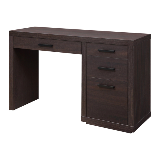
Writing desk
Hide thumbs
Also See for Steele Series:
- Assembly manual (36 pages) ,
- Assembly manual (36 pages) ,
- Assembly manual (24 pages)
Advertisement
Available languages
Available languages
Quick Links
If you have any questions regarding assembly or if parts are missing, DO NOT return this item to the
store where it was purchased. Please call our customer service number and have your instructions
and parts list ready to provide the model name, part name or factory number:
Pacific Standard Time: 8:30 a.m. - 4:30 p.m., Monday - Friday
Or visit our web site 24 hours a day, 7 days a week for product assistance at
THIS INSTRUCTION BOOKLET CONTAINS IMPORTANT SAFETY INFORMATION.
Steele Writing desk
Stock # BH46-084-599-01
ADULT ASSEMBLY REQUIRED
www.whalenstyle.com
Or e-mail your request to parts@whalenfurniture.com
PLEASE READ AND KEEP FOR FUTURE REFERENCE.
Date 2016-09-24 Rev. 0001-A Factory: HESLTD
866-942-5362
LOT NUMBER:
DATE PURCHASED:
/
/
Advertisement

Related Manuals for Better Homes and Gardens Steele Series


Summary of Contents for Better Homes and Gardens Steele Series
- Page 1 LOT NUMBER: DATE PURCHASED: Steele Writing desk Stock # BH46-084-599-01 ADULT ASSEMBLY REQUIRED If you have any questions regarding assembly or if parts are missing, DO NOT return this item to the store where it was purchased. Please call our customer service number and have your instructions and parts list ready to provide the model name, part name or factory number: 866-942-5362 Pacific Standard Time: 8:30 a.m.
-
Page 2: Special Note
M A X I M U M R E C O M M E N D E D W E I G H T L O A D S MANUFACTURER: Whalen Furniture Manufacturing CATALOG: Steele Writing desk (BH46-084-599-01) MADE IN CHINA MAXIMUM LOAD 200 lb. - Page 3 IMPORTANT Before you begin: Open, identify and count all parts prior to assembly. Lay out parts on a flat and non- abrasive surface. You will need the parts identified on page 4 and 5 of this instruction manual. NOTE: IT IS VERY IMPORTANT TO USE GLUE WITH DOWELS. EXCESS GLUE CAN BE WIPED OFF WITH DAMP CLOTH.
- Page 4 Parts and Hardware List Please read completely through the instructions and verify that all listed parts and hardware are present before beginning assembly. A- Top Panel (Qty. 1) B- Left Side Panel (Qty. 1) C- Partition Panel (Qty. 1) D- Right Side Panel (Qty. 1) E- Bottom Panel (Qty.
- Page 5 Parts and Hardware List Please read completely through the instructions and verify that all listed parts and hardware are present before beginning assembly. W- Right Middle Drawer Right Side X- Right Drawer Bottom Panel Y- File Drawer Front (Qty. 1) (Qty.
- Page 6 Right Upper Drawer Assembling Cam Bolt Small Cam Lock (4 used in this step) (4 used in this step) ② ⑥ 1. Unpack the unit and confirm that you have all the hardware and required parts. Assembly the unit on a carpeted floor or the empty carton to avoid any scratch.
- Page 7 Right Upper Drawer Assembling 4. Slide one Right Drawer Bottom Panel (X) into the grooves between the Drawer Side Panels (S1 and S2) until fully inserted into the Drawer Front (R).
- Page 8 Right Upper Drawer Assembling M4 x 38 mm Screw (4 used in this step) ⑦ 5. Fasten the Right Upper Drawer Back Panel (S) between the Drawer Side Panels (S1 and S2) with four 38 mm Screws (7). Make sure that Drawer Bottom Panel (X) fits securely into the groove of the Drawer Back Panel (S).
- Page 9 Right Upper Drawer Assembling Handle Bolt Handle (2 used in this step) (1 used in this step) ⑪ ⑩ 6. Turn the assembled drawer upright. 7. Attach one Handle (11) to the outside of the Drawer Front (R) with two Handle Bolts (10).
- Page 10 Right Middle Drawer Assembling Cam Bolt Small Cam Lock (4 used in this step) (4 used in this step) ② ⑥ 8. Securely screw 4 Cam Bolts (2) all the way into the designated small holes on the Right Middle Drawer Front (T).
- Page 11 Right Middle Drawer Assembling 10. Slide one Right Drawer Bottom Panel (X) into the grooves between the Drawer Side Panels (V and W) until fully inserted into the Drawer Front (T).
- Page 12 Right Middle Drawer Assembling M4 x 38 mm Screw (4 used in this step) ⑦ 11. Fasten the Right Middle Drawer Back Panel (U) to the Drawer Side Panels (V and W) with four 38 mm Screws (7). Make sure that Drawer Bottom Panel (X) fits securely into the groove of the Drawer Back Panel (U).
- Page 13 Right Middle Drawer Assembling Handle Bolt Handle (2 used in this step) (1 used in this step) ⑪ ⑩ 12. Turn the assembled drawer upright. 13. Attach the Handle (11) to the outside of the Drawer Front (T) with two Handle Bolts (10).
- Page 14 Left Drawer Assembling Small Cam Lock Cam Bolt (4 used in this step) (6 used in this step) ⑥ ② 14. Securely screw 6 Cam Bolts (2) into the designated small holes on the Left Drawer Front (L). 15. Connect the Left Drawer Side Panels (N and O) to the Drawer Front (L) by engaging four Small Cam Locks (6) (Refer to page 3 on Cam Lock system operation supplement).
- Page 15 Left Drawer Assembling Small Cam Lock (2 used in this step) ⑥ 16. Fasten the Left Drawer Bottom Support (Q) to the Drawer Front (L) with two Small Cam Locks (6).
- Page 16 Left Drawer Assembling 17. Slide the Left Drawer Bottom Panel (P) into the grooves between the Drawer Side Panels (N and O) until fully inserted into the Drawer Front (L).
- Page 17 Left Drawer Assembling M4 x 38 mm Screw (6 used in this step) ⑦ 18. Fasten the Left Drawer Back Panel (M) to the Drawer Side Panels (N and O) and Left Drawer Bottom Support (Q) with six 38 mm Screws (7). Make sure that Drawer Bottom Panel (P) fits securely into the groove of the Drawer Back Panel (M).
- Page 18 Left Drawer Assembling Handle Bolt Handle (2 used in this step) (1 used in this step) ⑪ ⑩ 19. Turn the assembled drawer upright. 20. Attach the Handle (11) to the outside of the Drawer Front (L) with two Handle Bolts (10).
- Page 19 File Drawer Assembling Cam Bolt Small Cam Lock M6 x 30 mm Wood Dowel (4 used in this step) (2 used in this step) (4 used in this step) ② ③ ⑥ 21. Securely screw 4 Cam Bolts (2) into the designated small holes on the File Drawer Front (Y). 22.
- Page 20 File Drawer Assembling 23. Slide the remainder Right Drawer Bottom Panel (X) into the grooves between the Drawer Side Panels (Y2 and Y3) until fully inserted into the Drawer Front (Y).
- Page 21 File Drawer Assembling M4 x 38 mm Screw (4 used in this step) ⑦ 24. Fasten the File Drawer Back Panel (Y1) between the Drawer Side Panels (Y2 and Y3) with four 38 mm Screws (7). Make sure that Drawer Bottom Panel (X) fits securely into the groove of the Drawer Back Panel (Y1).
- Page 22 File Drawer Assembling Handle Bolt Handle (2 used in this step) (1 used in this step) ⑪ ⑩ 25. Turn the assembled drawer upright. 26. Attach the Handle (11) to the outside of the Drawer Front (Y) with two Handle Bolts (10). 27.
- Page 23 Assembly Instructions Cam Bolt (18 used in this step) ② 28. Securely screw the Cam Bolts (2) into the designated small holes on the Top Panel (A), the Partition Panel (C) and the Side Panels (B and D) using a Phillips screwdriver.
- Page 24 Assembly Instructions M4 x 50 mm Screw M8 x 30 mm Wood Dowel (12 used in this step) (8 used in this step) ⑧ ④ 29. Attach the Bottom Short Supports (G) between the Bottom Long Supports (F) with four M8 x 30 mm Wood Dowels (4).
- Page 25 Assembly Instructions Large Cam Lock M8 x 30 mm Wood Dowel (2 used in this step) (2 used in this step) ① ④ 31. Attach the Short Crossbar (I) between the Panels (C and D) with two M8 x 30 mm Wood Dowels (4) and two Large Cam Locks (1).
- Page 26 Assembly Instructions M15 x 60 mm Wood Dowel M4 x 50 mm Screw (4 used in this step) (4 used in this step) ⑤ ⑧ 32. Attach the Bottom Panel (E) to the Panels (C and D) with four M15x 60 mm Wood Dowels (5) and four 50 mm Screws (8).
- Page 27 Assembly Instructions Large Cam Lock (8 used in this step) ① 33. Attach the Long Crossbar (J) and Back Upper Stretcher (K) to the Partition Panel (C) with four Large Cam Locks (1). 34. Repeat the same procedure to attach the Left Side Panel (B) at the opposite end.
- Page 28 Assembly Instructions M4 x 19 mm Metal Bracket Screw (4 used in this step) (2 used in this step) ⑫ ⑬ 35. Using the pilot holes as a guide, fasten two Metal Brackets (13) to the Top Panel (A) with four 19 mm Screws (12) as shown.
- Page 29 Assembly Instructions B/C/D Large Cam Lock M8 x 30 mm Wood Dowel M15 x 60 mm Wood Dowel (8 used in this step) (2 used in this step) (6 used in this step) ① ④ ⑤ 36. Insert six M15 x 60 mm Wood Dowels (5) into the top holes on the Panels (B, C and D) and insert two M8 x 30 mm Wood Dowels (4) into the top holes on the Back Upper Stretcher (K).
- Page 30 Assembly Instructions M4 x 19 mm Screw (4 used in this step) ⑫ 37. Insert four 19 mm Screws (12) through the Metal Brackets (13) and screw into the Left Side Panel (B).
- Page 31 Assembly Instructions M3.5 x 15 mm Washer Head Screw (14 used in this step) ⑨ 38. Now, go back and tighten all Cam Locks and Screws. Make sure that all the parts are tight and there are no gaps between the parts. This will help keep the unit square. 39.
- Page 32 Assembly Instructions 40. Ask for assistance to stand the unit upright and position at the desired location. 41. To insert the Right Utility Drawers inside the unit, tip the front of drawer down and drop the rollers of the drawer slide runners behind the rollers of slide tracks on the unit. Lift the front of the drawer up and slide it into the unit.
-
Page 33: Care And Maintenance
Care and Maintenance Use a soft, clean cloth that will not scratch the surface when dusting. Use of furniture polish is not necessary. Should you choose to use polish, test first in an inconspicuous area. Using solvents of any kind on your furniture may damage your furniture’s finish. Never use water to clean your furniture as it may cause damage to the finish. - Page 35 LOTE NÚMERO: FECHA DE COMPRA: / / Escritorio Steele Modelo # BH46-084-599-01 ENSAMBLE REQUERIDO POR ADULTO Si tiene alguna pregunta acerca del ensamble o si alguna parte está faltante, no retorne este producto a la tienda en que lo compró. Por favor llame a nuestro departamento de ayuda al cliente teniendo su instructivo y lista de partes para proveer el modelo, nombre de parte o el número de fábrica: 866-942-5362 Hora Estándar del Pacífico: 8:30 a.m.
- Page 36 M Á X I M O S P E S O S R E C O M E N D A D O S FABRICANTE: Whalen Furniture Manufacturing CATALOGO: Escritorio Steele (BH46-084-599-01) HECHO EN CHINA MÁXIMA CARGA 200 lb. (90.7 kg) MÁXIMA CARGA 10 lb.
- Page 37 Importante Antes de comenzar: Abra, identifique y cuente todas las partes antes del ensamble. Coloque las piezas sobre una superficie plana y no abrasiva. Tendrá que las partes identificadas en la página 4 y 5 de este manual de instrucciones. NOTA: ES MUY IMPORTANTE PARA EL USO DE GOMA CON LOS PERNSO DE MADERA.
- Page 38 Lista de partes y material de ferretería Por favor lea completamente las instrucciones y verifique que estén todas las partes antes de iniciar el ensamblado. A- Panel superior (Cant. 1) B- Panel lateral izquierdo (Cant. 1) C- Panel divisor (Cant. 1) D- Panel lateral derecho (Cant.
- Page 39 Lista de partes y material de ferretería Por favor lea completamente las instrucciones y verifique que estén todas las partes antes de iniciar el ensamblado. W- Lado derecho del cajón der. medio X- Panel inferior del cajón der. Y- Frente del cajón de archivos (Cant.
- Page 40 Ensamble del cajón derecho superior Tornillo de fijación Tuerca de fijación chica usados en este paso usados en este paso ② ⑥ 1. Desempacar la unidad y confirmar que se tiene todo el material de ferretería y partes requeridas. Ensamblar la unidad en un piso alfombrado o en el cartón vacío para evitar rasguños. 2.
- Page 41 Ensamble del cajón derecho superior 4. Deslizar un panel inferior del cajón derecho (X) en las ranuras entre los paneles laterales del cajón (S1 y S2) hasta que esté completamente insertado en el frente del cajón (R).
- Page 42 Ensamble del cajón derecho superior Tornillo de M4 x 38 mm usados en este paso ⑦ 5. Sujetar el panel posterior del cajón derecho superior (S) a los paneles laterales del cajón (S1 y S2) con 4 tornillos de 38 mm (7). Asegurar de que el panel inferior del cajón (X) queda en la ranura del panel posterior del cajón (S).
- Page 43 Ensamble del cajón derecho superior Tornillo de manija Manija usados en este paso usados en este paso ⑪ ⑩ 6. Poner el cajón ensamblado en posición vertical. 7. Adjuntar una manija (11) a la parte exterior del frente del cajón (R) con 2 tornillos de manija (10).
- Page 44 Ensamble del cajón derecho medio Tornillo de fijación Tuerca de fijación chica usados en este paso usados en este paso ② ⑥ 8. Colocar 4 tornillos de fijación (2) en los agujeros chicos designados en el frente del cajón derecho medio (T).
- Page 45 Ensamble del cajón derecho medio 10. Deslizar un panel inferior del cajón derecho (X) en las ranuras entre los paneles laterales del cajón (V y W) hasta que esté completamente insertado en el frente del cajón (T).
- Page 46 Ensamble del cajón derecho medio Tornillo de M4 x 38 mm usados en este paso ⑦ 11. Sujetar el panel posterior del cajón derecho medio (U) a los paneles laterales del cajón (V y W) con 4 tornillos de 38 mm (7). Asegurar de que el panel inferior del cajón (X) queda en la ranura del panel posterior del cajón (U).
- Page 47 Ensamble del cajón derecho medio Tornillo de manija Manija usados en este paso usados en este paso ⑪ ⑩ 12. Poner el cajón ensamblado en posición vertical. 13. Adjuntar una manija (11) a la parte exterior del frente del cajón (T) con 2 tornillos de manija (10).
- Page 48 Ensamble del cajón izquierdo Tuerca de fijación chica Tornillo de fijación usados en este paso usados en este paso ⑥ ② 14. Colocar 6 tornillos de fijación (2) en los agujeros chicos designados en el frente del cajón izquierdo (L). 15.
- Page 49 Ensamble del cajón izquierdo Tuerca de fijación chica usados en este paso ⑥ 16. Sujetar el soporte inferior del cajón izquierdo (Q) al frente del cajón (L) con 2 tuercas de fijación chicas (6).
- Page 50 Ensamble del cajón izquierdo 17. Deslizar un panel inferior del cajón izquierdo (P) en las ranuras entre los paneles laterales del cajón (N y O) hasta que esté completamente insertado en el frente del cajón (L).
- Page 51 Ensamble del cajón izquierdo Tornillo de M4 x 38 mm usados en este paso ⑦ 18. Sujetar el panel posterior del cajón izquierdo (M) a los paneles laterales del cajón (N y O) y al soporte inferior del cajón izquierdo (Q) con 6 tornillos de 38 mm (7). Asegurar de que el panel inferior del cajón (P) queda en la ranura del panel posterior del cajón (M).
- Page 52 Ensamble del cajón izquierdo Tornillo de manija Manija usados en este paso usados en este paso ⑪ ⑩ 19. Poner el cajón ensamblado en posición vertical. 20. Adjuntar una manija (11) a la parte exterior del frente del cajón (L) con 2 tornillos de manija (10).
- Page 53 Ensamble del cajón de archivos Tornillo de fijación Tuerca de fijación chica Perno de madera de M6 x 30 mm usados en este paso usados en este paso usados en este paso ② ③ ⑥ 21. Colocar 4 tornillos de fijación (2) en los agujeros chicos designados en el frente del cajón de archivos (Y).
- Page 54 Ensamble del cajón de archivos 23. Deslizar el panel inferior del cajón derecho restante (X) en las ranuras entre los paneles laterales del cajón (Y2 y Y3) hasta que esté completamente insertado en el frente del cajón (Y).
- Page 55 Ensamble del cajón de archivos Tornillo de M4 x 38 mm usados en este paso ⑦ 24. Sujetar el panel posterior del cajón de archivos (Y1) entre los paneles laterales del cajón (Y2 y Y3) con 4 tornillos de 38 mm (7). Asegurar de que el panel inferior del cajón (X) queda en la ranura del panel posterior del cajón (Y1).
- Page 56 Ensamble del cajón de archivos Tornillo de manija Manija usados en este paso usados en este paso ⑪ ⑩ 25. Poner el cajón ensamblado en posición vertical. 26. Adjuntar una manija (11) a la parte exterior del frente del cajón (Y) con 2 tornillos de manija (10). 27.
-
Page 57: Instrucciones De Ensamble
Instrucciones de ensamble Tornillo de fijación usados en este paso ② 28. Colocar los tornillos de fijación (2) en los agujeros chicos designados en el panel superior (A), en el panel divisor (C) y los paneles laterales (B y D) usando un desarmador estrella. - Page 58 Instrucciones de ensamble Tornillo de M4 x 50 mm Perno de madera de M8 x 30 mm usados en este paso usados en este paso ⑧ ④ 29. Adjuntar los soportes inferiores cortos (G) entre los soportes inferiores largos (F) con 4 pernos de madera de M8 x 30 mm (4).
- Page 59 Instrucciones de ensamble Tuerca de fijación grande Perno de madera de M8 x 30 mm usados en este paso usados en este paso ① ④ 31. Adjuntar el soporte corto (I) entre los paneles (C y D) con 2 pernos de madera de M8 x 30 mm (4) y 2 tuercas de fijación grandes (1).
- Page 60 Instrucciones de ensamble Perno de madera de M15 x 60 mm Tornillo de M4 x 50 mm usados en este paso usados en este paso ⑤ ⑧ 32. Adjuntar el panel inferior (E) a los paneles (C y D) con 4 pernos de madera de M15x 60 mm (5) y 4 tornillos de 50 mm (8).
- Page 61 Instrucciones de ensamble Tuerca de fijación grande usados en este paso ① 33. Adjuntar el soporte largo (J) y el soporte posterior superior (K) al panel divisor (C) con 4 tornillos de fijación grandes (1). 34. Repetir el mismo procedimiento para adjuntar el panel lateral izquierdo (B) al lado opuesto.
- Page 62 Instrucciones de ensamble Tornillo de M4 x 19 mm Soporte de metal usados en este paso usados en este paso ⑫ ⑬ 35. Usando los agujeros pilotos como guía, ajustar 2 soportes de metal (13) al panel superior (A) con 4 tornillos de 19 mm (12) como se muestra.
- Page 63 Instrucciones de ensamble B/C/D Tuerca de fijación grande Perno de madera de M8 x 30 mm Perno de madera de M15 x 60 mm usados en este paso usados en este paso usados en este paso ① ④ ⑤ 36. Insertar 6 pernos de madera de M15 x 60 mm (5) en los agujeros superiores en los paneles (B, C y D) e insertar 2 pernos de madera de M8 x 30 mm (4) en los agujeros superiores en el soporte posterior superior (K).
- Page 64 Instrucciones de ensamble Tornillo de M4 x 19 mm usados en este paso ⑫ 37. Insertar 4 tornillos de19 mm (12) a través de los soportes de metal (13) y atornillar en el panel lateral izquierdo (B).
- Page 65 Instrucciones de ensamble M3.5 x 15 mm Tornillo cabeza de arandela de usados en este paso ⑨ 38. Ahora, vuelva y apriete las tuercas de fijación y los tornillos. Asegurar de que las partes esten apretadas y de que no haya espacios entre las partes. Esto ayudara a mantener la unidad cuadrada. 39.
- Page 66 Instrucciones de ensamble 40. Pedir asistencia para posicionar la unidad ensamblada en posición vertical y en el lugar deseado. 41. Para insertar los cajones utilitarios derechos en la unidad, inclinar el frente del cajón para abajo y dejar caer las ruedas de las correderas del cajón atras de las ruedas de los rieles de corredera en la unidad. Levantar el frente del cajón hacia arriba y deslizar en la unidad.
-
Page 67: Mantenimiento Y Cuidados
Mantenimiento y Cuidados Use una toalla suave y limpia para evitar daños y rayaduras. El uso de cera para pulir muebles no es necesario. Si desea usar cera pruebe en un área que no sea visible para revisar su funcionamiento. Usar solventes de cualquier tipo puede dañar el acabado del mueble.
Need help?
Do you have a question about the Steele Series and is the answer not in the manual?
Questions and answers