
Subscribe to Our Youtube Channel
Related Manuals for Eton MICRO 250.4


Summary of Contents for Eton MICRO 250.4
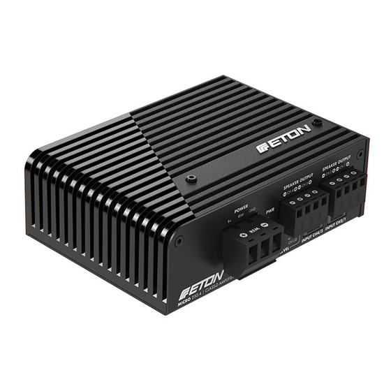
- Page 1 MICRO 250.4 MICRO 250.4 4-Kanal Micro Class-D Verstärker 4-channel micro Class-D amplifi er Einbauanleitung Instruction manual...
-
Page 2: Table Of Contents
CE-Certificate of Confirmity Technische Daten Technical Data Einführung Introduction ETON bedankt sich ausdrücklich für den Kauf ETON expressly thanks you for deciding to des Verstärkers und beglückwünscht Sie zu purchase this amplifier and congratulates you der Wahl dieses ausgezeichneten Produktes. -
Page 3: Sicherheitshinweise
Fahrt Gefahren auslösen. ETON übernimmt keine Verantwortung für ETON accepts no liability for hearing Gehörschäden, körperliche Schäden oder loss, bodily injury or property damage Sachschäden, die aus dem Gebrauch oder as a result of use or misuse of this Missbrauch seiner Produkte entstehen. -
Page 4: Verpackung Und Inhalt
Verpackung und Inhalt Table of contents Der Verstärker ist in einem dafür konstruierten The amplifier is packed into an especial- schützenden Karton verpackt. Beschädigen Sie ly constructed protecting carton. Do not die Verpackung nicht und bewahren Sie diese damage the packing and store it for future für die spätere Verwendung im Schadensfalle use in the case of possible damage. -
Page 5: Vorsichtsmaßregeln - Zuerst Lesen
Werkzeuge Tools Lautsprecher-, Strom- und Remotekabel Speaker wires in adequate lengths, in entsprechenden Längen, widths and colours Durchmessern und Farben HINWEIS: Wir empfehlen Kabel mit einem NOTE: We recommend to use power cable Querschnitt von 12 AWG (ca. 4 mm²) für die at least 12 AWG for (B+) and (GND) battery Strom- (B+) und Masse-Anschlüsse. - Page 6 Vorsichtsmaßregeln Precautions - Read first! Warnung! Die Verstärker sind ausschließlich Warning! The amplifiers are exclusively für den Innenbereich von Fahrzeugen konzi- designed for the interior of vehicles with a piert, die eine Stromversorgung von +12 Volt DC power supply of +12 volt DC (Direct Current). (Gleichspannung) aufweisen.
-
Page 7: Vor Dem Einbau
Vorsichtsmaßregeln Precautions - Read first! Achtung! Befestigen Sie den Verstärker an den Caution! Mount the amplifier using the three drei Befestigungspunkten. Achten Sie auf eine fastening points. Be careful that you choose a feste stabile Grundfläche die der Belastung strong, stable surface that can carry the weight standhalten kann. - Page 8 Vor dem Einbau Before Installation Vorsicht! Vermeiden Sie es, Stromkabel in Caution! Avoid running power wires near der Nähe von NF (Cinch) oder Antennen- the low level input cables, antenna, power kabeln, oder empfindlichem Geräten oder leads, sensitive equipment or harnesses. Halterungen zu verlegen.
- Page 9 Vor dem Einbau Before Installation 8. Schützen Sie die Batterie und das elektrische 8. ALWAYS protect the battery and electrical System IMMER durch ordnungsgemäße system from damage with proper fusing. Sicherungen vor Schäden. Installieren Sie Install the appropriate fuse holder and fuse die entsprechende Sicherungshalterung und on the +12 V power wire within 18“...
-
Page 10: Einbau Und Verkabelung
Einbau und Verkabelung Installation and wiring HIGH-POWER OUTPUT 2 x 80 W @ 4 ohms... - Page 11 Einbau und Verkabelung Installation and wiring ANSCHLÜSSE FRONTSEITE CONNECTIONS FRONT 1) Masseanschluss Strom (-12V / GND) 1) Ground connection current (-12V / GND) 2) Plus-Polanschluss (+12 V / B+) 2) Positive pole connection (+12 V / B+) 3) REM ACC Remote Eingang 3) REM ACC remote input 4) Lautsprecher Ausgänge (Kanal 1+2) 4) Speaker Outputs (Channel 1 + 2)
- Page 12 Einbau und Verkabelung Installation and wiring Empfehlungen für alle Class D Endstufen Recommendations for all Class D amplifiers Alle Class D Endstufen senden aufgrund ihres Class D amplifiers by the nature of their Schaltunglayouts einen gewissen Anteil an design emit a certain amount of RF (Radio Funkwellen im Radioband.
- Page 13 Einbau und Verkabelung Installation and wiring Nehmen Sie Ihr Fahrzeug nicht in Do not use your automobile until all Betrieb, bevor alle Komponenten des components of the system have been Systems fest und sicher eingebaut secured to the interior framework. sind.
- Page 14 Gewöhnliche elektrische systems which are in good condition should Systeme, die sich in gutem Zustand befinden, be able to handle the extra load of any ETON sollten in der Lage sein, die zusätzliche Be- amplifier without problems, although battery lastung durch einen beliebigen Verstärker aus...
- Page 15 Einbau und Verkabelung Installation and wiring Planen Sie die Kabelverlegung. Die RCA-Kabel Plan the wire routing. Keep RCA cables (Cinch) sollen dicht zusammen bleiben, aber close together but isolated from the amplifier‘s von den Stromkabeln des Verstärkers und power cables and any high power auto anderem Hochleistungszubehör, insbesondere accessories, especially electric motors.
- Page 16 Einbau und Verkabelung Installation and wiring...
- Page 17 Einbau und Verkabelung Installation and wiring...
- Page 18 Einbau und Verkabelung Installation and wiring Das ROTE Kabel (Stromkabel) maximal Trim the RED wire (power cable) within 45 cm von der Batterie abisolieren und 18“ of the battery and splice in a inline fuse einen Inline-Sicherungshalter (nicht im holder (not supplied). See Specifications Lieferumfang) einspleißen/ montieren.
- Page 19 Schalter in eine Leitung mit einer 12 V - Quelle line with a 12 V source to activate the amplifier. einzubauen, um den Verstärker zu aktivieren. The MICRO 250.4 amplifier is equipped with Der MICRO 250.4 Verstärker verfügt über an automatic switch-on signal detection, which...
- Page 20 EINGANGSSIGNAL WÄHLEN SET INPUT SIGNAL Sie können den MICRO 250.4 Verstärker mit You can operate the MICRO 250.4 amplifier with zwei unterschiedlichen Arten des Quellsignals two different types of source signal. You can either betreiben. Dabei können Sie entweder einen...
- Page 21 Einbau und Verkabelung Installation and wiring HIGH-LEVEL SIGNAL TAP HIGH-LEVEL SIGNALABGRIFF To feed a high-level / hi-level signal into the Um ein High-Level / Hi-Level Signal in den Ver- amplifier, the supplied High-Level / Hi-Le- stärker einzuspeisen, wird das mitgelieferte High- Level / Hi-Level Input Adapter Kabel benötigt.
- Page 22 Einbau und Verkabelung Installation and wiring Eingangssignal 4-Kanal High-Level/Hi-Level + - - + + - - + 2 Stück im Set enthalten 2 pcs. included CH4/3 CH2/1 Eingangssignal 2-Kanal High-Level/Hi-Level + – Links/Left Rechts/Right Links/Left Rechts/Right CH2+CH4 CH1+CH3 High-/Level Input High-/Level Input Rechts/Right Channel Links/Left Channel...
- Page 23 Einbau und Verkabelung Installation and wiring HIGH-LEVEL 4-Kanal HIGH-LEVEL 4-channel Sie können den Verstärker mit unterschied- You can use the amplifier with different input lichen Eingangssignalen nutzen, beispielsweise signals, for example if you connect a front system wenn Sie ein Front-System und Hecksys- and rear system, but both systems receive a tem anklemmen, beide Systeme erhalten separate input signal from the headunit (front...
- Page 24 Einbau und Verkabelung Installation and wiring Achtung! Stets gewährleisten, dass die Attention. Always make sure that the Zündung ausgeschaltet oder das Strom- ignition is switched off or the power kabel vom Verstärker abgezogen ist, cable is disconnected from the amplifier bevor RCA-Kabel (Cinch) angeschlossen before connecting RCA cables.
- Page 25 Einbau und Verkabelung Installation and wiring 4-KANAL EINGANGS-SIGNAL 2-KANAL EINGANGS-SIGNAL RCA / RCA / LOW-LEVEL LOW-LEVEL BRIDGED MODE CABLE LOW-LEVEL INPUT BRIDGED MODE 2 Stück im Set enthalten 1 Stück im Set enthalten 2 pcs. included 1 pcs. included...
- Page 26 Einbau und Verkabelung Installation and wiring DIE LAUTSPRECHER ANSCHLIESSEN CONNECT THE SPEAKERS Von den Enden der Lautsprecherkabel 0,5 Remove 0.5 cm of insulation from the ends cm Isolation abziehen, dann die Kabel in die of the speaker cables, then insert the cables Lautsprecheranschluss-Stecker einführen und into the speaker connector plugs and tighten die Befestigungsschrauben fest anziehen.
-
Page 27: Einstellungen
Einbau und Verkabelung Installation and wiring Eine abschließende Prüfung des gesam- Perform a final check of the completed ten Kabelsystems durchführen, um zu system wiring to ensure that all connections gewährleisten, dass alle Verbindungen are accurate. Check all power and ground akkurat sind. - Page 28 Einstellungen Adjustment GAIN / LEVEL EINSTELLUNG (G) GAIN / LEVEL SETTING (G) CH1/2 & CH3/4 LEVEL= Gain-Regler ermög- CH1/2 & CH3/4 LEVEL= Gain control allows licht die Einstellung der Eingangsempfindlich- to adjust the input sensitivity for channel pairs keit für die Kanalpaare CH1/2 & CH3/4. Bitte CH1/2 &...
- Page 29 Einstellungen Adjustment AKTIVE FILTER / TRENNFREQUENZEN (H) ACTIVE FILTERS / X-OVER FREQUENCIES (H) Die MICRO 250.4 Endstufe verfügt unter der The MICRO 250.4 power amplifier has Active Schutzabdeckung auf der Oberseite über Aktive Filters setting options for the channel pairs Filter Einstellmöglichkeiten für die Kanalpaare...
-
Page 30: Fehlerbehebung
Fehlerbehebung Troubleshooting Hinweis: Falls Sie nach dem Einbau Proble- Note: If you are having problems after instal- me haben, befolgen Sie die nachfolgenden lation follow the Troubleshooting procedures Verfahren zur Fehlerbeseitigung: below. Verfahren 1: Procedure 1: Den Verstärker auf ordnungsgemäße Anschlüs- Check Amplifier for proper connections. - Page 31 Lichtmaschine und Batterie des Fahrzeugs die erforderliche Spannung aufrecht erhält. Soll- te keiner dieser Schritte Abhilfe schaffen, ist der Verstärker möglicherweise defekt. Wenden Sie sich an einen ETON Vertragshändler. Verfahren 3: Procedure 3: Den Verstärker auf Audioleistung überprüfen. Check Amplifier for audio output.
- Page 32 Fehlerbehebung Troubleshooting Verfahren 4: Procedure 4: Prüfen Sie, ob beim Einschalten des Verstärkers Check Amplifier if you experience Turn-on ein Knacken auftritt. Pop. 1 . Das Eingangssignal (Cinchkabel) zum Ver- 1. Disconnect input signal to amplifier and stärker entfernen und den Verstärker ein- und turn amplifier on and off.
- Page 33 Fehlerbehebung Troubleshooting des Metall ist, das frei von Farbe, Rost usw. ist. ODER 4. Ein zweites Massekabel vom Negativpol der 4. Add secondary ground cable from negative Batterie zum Fahrgestellsmetall oder Motorblock battery terminal to the chassis metal or engine des Fahrzeugs hinzufügen.
-
Page 34: Ce-Konformitätszeugnis
The following product has been tested by us with the listed standards and found in conformity with the council EN 55032:2012. It is possible to use CE marking to EN 55032:2015 demonstrate the conformity with this EMC Directive. Manufacturer ETON Car-Audio GmbH Dinkelweg 6, 89233 Neu-Ulm, Germany Address: Pfaffenweg 21, 89231 Neu-Ulm Trade Mark ETON MICRO 250.4... -
Page 35: Technische Daten
Technische Daten Modell MICRO 250.4 Advanced Class-D Verstärker 4-Kanal mit asymmetrischer Leistungsverteilung Leistung an 4 Ohm 2 x 45 W (RMS) Leistung an 4 Ohm (High-Power) 2 x 80 W (RMS) Leistung an 2 Ohm / Brückenbetrieb nicht unterstützt! HPF / Hochpass-Filter 50 Hz –... -
Page 36: Technical Data
Dimensions (L x W x H) in mm 127 x 94 x 42 mm ETON behält sich das Recht vor, die beschriebenen Produkte ohne jegliche Vorankündigung zu ver- ändern oder zu verbessern. Alle Rechte sind vorbehalten. Die auch teilweise Vervielfältigung des vorliegenden Handbuchs ist untersagt.
Need help?
Do you have a question about the MICRO 250.4 and is the answer not in the manual?
Questions and answers