Table of Contents

Subscribe to Our Youtube Channel
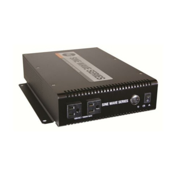
Related Manuals for ICT Sine Wave ICT1500-12W


Summary of Contents for ICT Sine Wave ICT1500-12W
- Page 1 All manuals and user guides at all-guides.com Innovative Circuit Technology Ltd. 1500W Sine Wave Series Inverter INSTRUCTION MANUAL 855-151-000 Models: ICT1500-12SW ICT1500A-12SW ICT1500-24SW ICT1500A-24SW ICT1500-48SW ICT1500A-48SW...
- Page 2 Do not attempt to service any internal parts. Refer all product service to an authorized ICT Ltd. service facility CAUTION Risk of personal injury or damage to equipment! Always observe the following: ...
-
Page 3: Table Of Contents
All manuals and user guides at all-guides.com Contents INTRODUCTION .................. 4 INSTALLATION ..................4 OPERATION ..................8 Status Indicators and Alarms ............9 AC Transfer Switch (Option “T”) ..........10 TCP/IP WEB BASED UTILITY OPTION ..........11 Status and Control ............... 12 Device Setup ................ -
Page 4: Introduction
ICT1500-48SWTC ICT1500A-48SWTC Ethernet/SNMP option Optional Accessories: 19 inch rack mounting kit (mount up to 2 inverters): ICT-RMK4 Wiring Junction Box (attaches to back of inverter): ICT-DCWB INSTALLATION Perform a quick physical check of the unit as it is being taken out of the box to ensure it has not been damaged during shipping. - Page 5 Mount the optional wiring junction box base (part of the Wiring Junction Box kit ICT-DCWB) to the back of the inverter with 4 supplied screws, as shown in Figure 1. Knockout the plugs and install conduit fittings or wire strain relief clamps in the wiring box openings to be used for the installation, as required.
- Page 6 All manuals and user guides at all-guides.com The inverter may be mounted horizontally on a shelf, or the ICT rack tray, or in a vertical wall mounted orientation. Install the unit with either side located on top (as shown in Figure 3) when wall mounting to ensure proper cooling and long term safe operation of the inverter.
- Page 7 All manuals and user guides at all-guides.com POS Input from NEG Input from Battery with Battery Breaker or Fuse External AC Input Alarm Contacts AC Output to load 10/100 Base-T (Option “T”) L-N-G C-NC-NO L-N-G Ethernet Port (Option “C”) AC Transfer V 15A Output Circuit Setting Switch Breaker...
-
Page 8: Operation
All manuals and user guides at all-guides.com CAUTION Risk of personal injury or damage to equipment! AC input wiring from the grid or other power source to the inverter must be protected using a branch rated circuit breaker of 15A or lower value. Connect the external alarm monitoring wiring to the Form-C alarm contact output if desired. -
Page 9: Status Indicators And Alarms
All manuals and user guides at all-guides.com Inverter On/Off Switch Green AC Indicator AC Outlets: Red - Fault - Inverter on (flash) 2 x NEMA 5-15R (115V) - Grid power (continuous) Or 1 x IEC type I (230V) Yellow - Low Battery Warning Figure 5: Front Panel Status Indicators and Alarms... -
Page 10: Ac Transfer Switch (Option "T")
All manuals and user guides at all-guides.com Shutdown Voltage drops below 10.5/21.0/42.0VDC for 1 s. Clears when Input Voltage rises above warning level for 1 s. DC Overvoltage Triggers when Input Shutdown Voltage rises above 16.5/33/66VDC for 1 s. Clears when Input Voltage drops below 16.0/32/64VDC for 1 s. -
Page 11: Tcp/Ip Web Based Utility Option
IP address. Run the utility on a Windows computer connected to the same network as the inverter, and it will report the IP addresses of all ICT units connected to that network. The inverter will otherwise use the factory default IP address of 192.168.0.180, as shown above. -
Page 12: Status And Control
All manuals and user guides at all-guides.com Figure 6: Typical Inverter Login Screen Your browser will then be logged in to the inverter and the Status and Control page for the unit will be displayed as shown below. See the following section for descriptions on how to use the various monitoring and control features available through the inverter’s graphical web interface. -
Page 13: Device Setup
Figure 8: Device Setup Page Device Info: Device Name: Enter a custom descriptive name for the inverter, if desired Model: Displays the ICT model number for the inverter Hardware: Displays the hardware version of the inverter Network Watchdog: Watchdog Enabled: Checking this box will enable the watchdog feature, which will cause the unit to periodically ping up to two remote IP addresses to verify the network connection status. -
Page 14: Network Setup
All manuals and user guides at all-guides.com Secondary IP Address: Enter an optional second IP address that the unit can monitor to verify network status. The Network Watchdog will only trigger if both the Primary and Secondary IP addresses fail to respond. Watchdog Timeout: Enter the time (1 to 80 minutes) that the remote IP address must stop responding to ping requests from the inverter, before the Network Watchdog will trigger an inverter output power cycle. - Page 15 All manuals and user guides at all-guides.com NOTE: Saving any changes to the network settings will cause the inverter to re-boot, cycling power to the output. Network: MAC Address: Displays the MAC address assigned to the inverter. Enable DHCP: Turn on this setting if your network uses a DHCP server to automatically assign IP addresses.
- Page 16 All manuals and user guides at all-guides.com To access the inverter through a secure HTTPS connection, use https:// at the start of the units URL. (e.g. https://192.168.0.180:8888 for IP address 192.168.0.180, HTTPS port 8888) UDP Port: This port is used when applying firmware upgrades to the inverter.
-
Page 17: E-Mail Setup
All manuals and user guides at all-guides.com SNMP Contact Information: Assign contact information, such as an operator name and phone number for the inverter, which can be read via SNMP queries. (This information is optional) Click on the Save Settings button at the bottom of the page to save any changes and re-boot the unit. -
Page 18: User Setup
All manuals and user guides at all-guides.com Recipient E-mail Addresses: Enter one or more e-mail addresses that are to receive all e-mail notifications from the inverter. Use commas to separate multiple addresses. This field can also be used to send a text message notification to a phone;... - Page 19 All manuals and user guides at all-guides.com Figure 11: User Setup Page The unit has no password assigned by default, so an Administrator password should be assigned to your inverter for improved security. NOTE: Record your new password for future access! If the Administrator password is lost the unit must be reset to return the password to the blank default setting, causing loss of all other user settings.
-
Page 20: Maintenance
All manuals and user guides at all-guides.com Maintenance Use this page to reset the inverter communications port (soft reset), restore its factory default settings, or send a test e-mail to verify e-mail functionality. Figure 12: Maintenance Page Reset Communications: Clicking the Reset button will restart the communication processor, resetting the Ethernet communication port without interrupting the AC output. -
Page 21: Mobile Web App
All manuals and user guides at all-guides.com MOBILE WEB APP Use the mobile version of the Status and Control page to monitor and control the inverter with a smartphone web browser. Access the Mobile Web App by entering the address of the inverter in the address field of your browser, followed by “/m”. -
Page 22: Router Configuration
All manuals and user guides at all-guides.com Comm Reset Button ROUTER CONFIGURATION Use this section to set up an inverter with remote Internet access when located behind a router. A router allows multiple PC’s to share a single Internet connection, and must be configured correctly to forward incoming remote data to the local IP address of your inverter. - Page 23 All manuals and user guides at all-guides.com 4. Set up your router to allow remote firmware upgrades to the inverter by repeating steps 2a to 2e with the UDP port number the inverter is using. (default UDP port is 9393) This step is optional if firmware upgrades are to be done locally.
-
Page 24: Text Message Alarm Notifications
IP address. Run the utility on a Windows computer connected to the same network as the inverter, and it will report the IP addresses of all ICT units connected to that network. The IP address may have been changed if DHCP is enabled. - Page 25 All manuals and user guides at all-guides.com IP address of 192.168.0.180 the typical network settings for your computer are: IP Address: 192.168.0.180 Subnet Mask: 255.255.255.0 Gateway: 192.168.0.1 If the HTTP port of the inverter has been changed, you must append the new port number to the URL used to access the unit.
-
Page 26: Product Specifications
All manuals and user guides at all-guides.com PRODUCT SPECIFICATIONS Continuous Output Power: 1500W Surge Power (2 seconds): 3000W Peak Efficiency (typical): Input Voltage: 12V model 10.5 to 16.0Vdc 24V model 21.0 to 32.0Vdc 48V model 42.0 to 64.0Vdc Battery Low Shutdown: 12V model 10.5Vdc 24V model... - Page 27 All manuals and user guides at all-guides.com Front AC Outlet (115Vac models): 2 NEMA 5-15R, 120V 15A Front AC Outlet (230Vac “A” models): 1 IEC Type I, 230V 10A Alarm Connector: Removable plug, cage clamp type 16 – 28AWG Operating Temperature Range: -20C to +40C Humidity: 10 –...
-
Page 28: Limited Warranty
The user of ICT products, which are to be used in life support applications as described above, assumes all risks of such use and indemnifies ICT against all damages.
Need help?
Do you have a question about the Sine Wave ICT1500-12W and is the answer not in the manual?
Questions and answers