Table of Contents
Advertisement
Quick Links
Advertisement
Table of Contents

Related Manuals for Aaeon EMB-APL1-A10-3350-F1-LV


Summary of Contents for Aaeon EMB-APL1-A10-3350-F1-LV
- Page 1 EMB-APL1...
- Page 2 E15335 Revised Edition V3 March 2019 Copyright Notice This document is copyrighted, 2019. All rights are reserved. The original manufacturer reserves the right to make improvements to the products described in this manual at any time without notice. No part of this manual may be reproduced, copied, translated, or transmitted in any form or by any means without the prior written permission of the original manufacturer.
-
Page 3: Table Of Contents
Contents Chapter 1: Product overview Package contents ................. 1-1 Features ..................1-1 1.3 Specifications ................1-2 Chapter 2: Motherboard information Before you proceed ..............2-1 Motherboard layout ..............2-2 Screw size ..................2-5 2.3.1 Component side .............. 2-5 2.3.2 Solder side ..............2-6 Central Processing Unit (CPU) ........... - Page 4 Contents 3.5.1 Administrator Password ..........3-10 3.5.2 User Password .............. 3-10 Boot menu .................. 3-11 3.6.1 Boot Configuration ............3-11 3.6.2 Boot Option Priorities ............ 3-11 Save & Exit menu ............... 3-11 Appendix Notices .......................A-1...
-
Page 5: Chapter 1: Product Overview
Chapter 1 Product overview Package contents Check your industrial motherboard package for the following items. 1 x Industrial Motherboard 1 x SATA cable 1 x SATA power cable 1 x I/O shield 1 x Support DVD NOTE: If any of the above items are damaged or missing, contact your distributor or sales representative immediately. -
Page 6: Specifications
1.3 Specifications SYSTEM N4200, (4C @ 2.50GHz CPU [Burst Mode], 750MHz GFX [Turbo], ~6W TDP) N3350, (2C @ 2.40GHz CPU [Burst Mode], 650MHz GFX [Turbo], ~6W TDP) E3930, (2C @ 1.80GHz CPU [Burst Mode], 550MHz GFX [Turbo], ~6.5W TDP) Memory 2 x SO-DIMM, max. - Page 7 Storage 2 x SATA 6Gb/s (1 colay with M.2) (default: 1 x SATA + M.2) 1 x SATA power connector (5V / 12V @1A) 2 x USB 3.0 ports (at the back panel) 5 x USB 2.0 ports (2 at the back panel, 3 at the mid-board) Display I/O 1 x VGA, 1 x HDMI, 1 x eDP (colay with LVDS) Audio I/O...
- Page 8 Others Supported OS Windows 10 64-bit ® Ubuntu16.04.02 / Kernel4.8.0 Accessories 1 x SATA cable 1 x SATA power cable 1 x I/O shield 1 x Support DVD NOTE: Specifications are subject to change without notice. EMB-APL1...
-
Page 9: Chapter 2: Motherboard Information
Chapter 2 Motherboard information Before you proceed Take note of the following precautions before you install motherboard components or change any motherboard settings. CAUTION! • Unplug the power cord from the wall socket before touching any component. • Before handling components, use a grounded wrist strap or touch a safely grounded object or a metal object, such as the power supply case, to avoid damaging them due to static electricity. • Hold components by the edges to avoid touching the ICs on them. • Whenever you uninstall any component, place it on a grounded antistatic pad or in the bag that came with the component. -
Page 10: Motherboard Layout
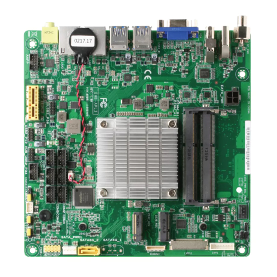
Motherboard layout NOTE: Place four screws into the holes indicated by circles to secure the motherboard to the chassis. CAUTION! Do not overtighten the screws! Doing so can damage the motherboard. 17.0cm(6.7in) BKL_PWR DC_PWR1 SYS_FAN1 HDMI1 DC_PWR2 DDR3 SO-DIMM_B1 (64bit, 204-pin module) VGA1 DDR3 SO-DIMM_A1 (64bit, 204-pin module) M2E1 USB1 Intel ®... - Page 11 Chapter 2: Motherboard information...
- Page 12 Connectors/Jumpers/Slots/LEDs Page DCIN AUX power connector (4-pin DC_PWR2) 2-13 DDR3L SO-DIMM slots Chassis fan connector (4-pin SYS_FAN1) 2-12 LVDS panel voltage selection jumper (3-pin LVDS_PWR) Inverter voltage selection jumper (3-pin BKL_PWR) Inverter backlight control mode selection jumper (3-pin J3) Backlight inverter power connector (8-pin INV1) 2-17 LVDS connector (40-pin LVDS1) 2-15 M.2 E Key and M Key slots 2-16 Integrated Intel Apollo Lake processor N4200/N3350/E3930 ® Serial ATA 6.0Gb/s connectors (7-pin SATA6G_1~2) 2-14 SATA power connector (4-pin SATA_PWR1) 2-17 System panel connector (10-1 pin F_PANEL1) 2-13 AT/ATX mode selection (3-pin ATX_AT1) 2-10 Clear RTC RAM (3-pin CLRTC1) PS/2 keyboard/mouse connector (6-pin KBMS1) 2-17 Chassis intrusion jumper (4-1 pin CHASSIS1) 2-10 Digital I/O connector (10-pin DIO1) 2-16 USB 2.0 connectors (10-pin USB2_P1, USB2_P2) 2-14 Serial port connectors (10-pin COM1~6) 2-18 Battery connector (2-pin BATTERY1) 2-19 SPI programming connector (8-pin SPI1) 2-15 Embedded DisplayPort (Bottom, 40-pin EDP1)
-
Page 13: Screw Size
Screw size 2.3.1 Component side 170.18 166.85 164.97 161.54 164.47 159.16 157.25 157.25 152.05 149.73 147.25 147.25 145.07 140.34 137.25 137.25 132.08 130.84 128.40 119.19 119.12 109.85 105.47 102.09 96.05 91.76 89.18 85.69 74.26 61.60 53.41 45.45 30.08 11.84 21.82 11.10 10.49 16.04... -
Page 14: Solder Side
2.3.2 Solder side 170.18 165.10 165.10 159.13 121.85 70.85 33.02 10.16 0.00 EMB-APL1... -
Page 15: Central Processing Unit (Cpu)
Central Processing Unit (CPU) The motherboard comes with an integrated Intel Apollo Lake processor N4200/ ® N3350/E3930. Intel ® Apollo Lake EMB-APL1 EMB-APL1 CPU System memory This motherboard comes with two Double Data Rate 3 Low Voltage (DDR3L) Small Outline Dual Inline Memory Modules (SO-DIMM) sockets. The figure illustrates the location of the DDR3L DIMM sockets: DIMM_B1 DIMM_A1 EMB-APL1 EMB-APL1 204-pin DDR3 So-DIMM sockets Installing a DIMM To install a DIMM To remove a DIMM Chapter 2: Motherboard information... -
Page 16: Jumpers
Jumpers Clear RTC RAM (3-pin CLRTC1) This jumper allows you to clear the Real Time Clock (RTC) RAM in CMOS. You can clear the CMOS memory of date, time, and system setup parameters by erasing the CMOS RTC RAM data. The onboard button cell battery powers the RAM data in CMOS, which include system setup information such as system passwords. EMB-APL1 EMB-APL1 Clear RTC RAM To erase the RTC RAM: 1. Turn OFF the computer and unplug the power cord. 2. Move the jumper cap from pins 1-2 (default) to pins 2-3. Keep the cap on pins 2-3 for about 5~10 seconds, then move the cap back to pins 1-2. 3. Plug the power cord and turn ON the computer. 4. Hold down the <Del> key during the boot process and enter BIOS setup to reenter data. CAUTION! Except when clearing the RTC RAM, never remove the cap on CLRTC jumper default position. Removing the cap will cause system boot failure! NOTE: If the steps above do not help, remove the onboard battery and move the jumper again to clear the CMOS RTC RAM data. After clearing the CMOS, reinstall the battery. - Page 17 Inverter voltage selection jumper (3-pin BKL_PWR) BKL_PWR +12V (Default) EMB-APL1 EMB-APL1 Inverter voltage selection Pins +12V +5V (Default) Inverter backlight control mode selection jumper (3-pin J3) DC mode PWM mode (Default) EMB-APL1 EMB-APL1 Inverter backlight control mode selection Pins DC mode (Default) PWM mode Chapter 2: Motherboard information...
- Page 18 AT/ATX mode selection jumper (3-pin ATX_AT1) ATX_AT1 EMB-APL1 EMB-APL1 AT/ATX mode selection Pins ATX mode (Default) AT mode Chassis intrusion jumper (4-1 pin CHASSIS1) This connector is for a chassis-mounted intrusion detection sensor or switch. Connect one end of the chassis intrusion sensor or switch cable to this connector. The chassis intrusion sensor or switch sends a high-level signal to this connector when a chassis component is removed or replaced. The signal is then generated as a chassis intrusion event. Move the jumper cap to pins 1-2 when you intend to use the chassis intrusion detection feature. CHASSIS EMB-APL1 PIN1 EMB-APL1 Chassis intrusion connector...
-
Page 19: Connectors
Connectors 2.7.1 Rear panel connectors DC power port. This port connects to a DC power adapter. HDMI port. This port is for a High-Definition Multimedia Interface (HDMI) connector, and is HDCP compliant allowing playback of HD DVD, Blu-Ray, and other protected content. Video Graphics Adapter (VGA) port. This 15-pin port is for a VGA monitor or other VGA-compatible devices. USB 3.0 ports. These 9-pin Universal Serial Bus (USB) ports connect to USB 3.0/2.0 devices. NOTES: • DO NOT connect a keyboard / mouse to any USB 3.0 port when installing Windows operating system. ® • Due to USB 3.0 controller limitation, USB 3.0 devices can only be used under Windows OS environment and after the USB 3.0 driver installation. ® • We strongly recommend that you connect USB 3.0 devices to USB 3.0 ports for faster and better performance for your USB 3.0 devices. USB 2.0 ports. These two 4-pin Universal Serial Bus (USB) ports are available for connecting USB 2.0/1.1 devices. -
Page 20: Internal Connectors
2.7.2 Internal connectors Chassis fan connector (4-pin SYS_FAN1) Connect the fan cable to the fan connector on the motherboard, ensuring that the black wire of each cable matches the ground pin of the connector. SYS_FAN1 EMB-APL1 PIN 1 EMB-APL1 Fan connector CAUTION: DO NOT forget to connect the fan cable to the fan connector. Insufficient air flow inside the system may damage the motherboard components. This is not a jumper! DO NOT place a jumper cap on the fan connector. Embedded DisplayPort (40-pin EDP1) This connector is for an internal embedded DisplayPort connection. EDP1(Bottom) PIN 1 eDP_TXN3_C... - Page 21 DCIN AUX power connector (4-pin DC_PWR2) This port connects to a DCIN AUX supply plug. The power supply plug is designed to fit this connector in only one orientation. Find the proper orientation and push down firmly until the connector completely fits. DC_PWR2 PIN 1 EMB-APL1 EMB-APL1 DCIN AUX power connector System panel connector (10-1 pin F_PANEL1) This connector supports several chassis-mounted functions. F_PANEL1 (NC) RSTCON#_PANEL PWRBTN# PWR_LED- HDD_LED- PWR_LED+ HDD_LED+ PIN 1 EMB-APL1 EMB-APL1 System panel connector •...
- Page 22 Serial ATA 6.0Gb/s connector (7-pin SATA6G_1~2) These connectors connect to Serial ATA 6.0 Gb/s hard disk drives via Serial ATA 6.0 Gb/s signal cables. EMB-APL1 EMB-APL1 SATA 6.0Gb/s connectors USB 2.0 connectors (10-pin USB2_P1, USB2_P2) These connectors are for USB 2.0 ports. Connect the USB module cable to any of these connectors, then install the module to a slot opening at the back of the system chassis. These USB connectors comply with USB 2.0 specification that supports up to 480 Mbps connection speed. USB2_P1 USB2_P2 PIN 1 PIN 1 EMB-APL1 EMB-APL1 USB2.0 connectors CAUTION! Never connect a 1394 cable to the USB connectors. Doing so will damage the motherboard! NOTE: The USB module cable is purchased separately. EMB-APL1 2-14...
- Page 23 LVDS connector (40-pin LVDS1) This connector is for an LCD monitor that supports Low-voltage differential signaling (LVDS) interface. LVDS1 PIN 40 SPD1 +BLVCC +BLVCC +BLVCC LVDS1_CLK- LVDS1_CLK+ VCON INV_ENABKL SPC1 LVDS0_CLK- LVDS0_CLK+ +V_PANEL +V_PANEL +V_PANEL LVDS1_D0- LVDS1_D0+ LVDS1_D1- LVDS1_D1+ LVDS1_D2- LVDS1_D2+ LVDS1_D3- LVDS1_D3+ LVDS0_D0- LVDS0_D0+ LVDS0_D1- LVDS0_D1+ LVDS0_D2- LVDS0_D2+ EMB-APL1 LVDS0_D3- LVDS0_D3+ PIN 1 EMB-APL1 LVDS connector SPI programming connector (8-pin SPI1)
- Page 24 M.2 socket 3 The M2E1 socket allows you to install a PCIe interface M.2 (NGFF) E Key module. The M2M1 socket allows you to install a SATA interface M.2 (NGFF) M Key SSD module. M.2(SOCKET3) 2230 M2E1 M2M1 EMB-APL1 2242 EMB-APL1 M.2 sockets The M.2 (NGFF) module is purchased separately. 10. Digital I/O connector (10-pin DIO1) This connector includes 8 I/O lines (In/Out programmable). All of the Digital I/O lines are programmable and each I/O pin can be individually programmed to support various devices. DIO1 EMB-APL1 PIN 1 EMB-APL1 Digital I/O connector NOTE: To configure the I/O pins in BIOS, go to the Advanced tab > Digital IO Port Configuration > DIO Port 1~8. See section 3.3.8 Digital IO Port Configuration for details.
- Page 25 11. PS/2 keyboard/mouse connector (6-pin KBMS1) This connector is for an IBM PS/2-compatible keyboard and mouse. KBMS1 PIN 1 EMB-APL1 EMB-APL1 PS/2 keyboard/mouse connector 12. SATA power connector (4-pin SATA_PWR1) This connector is for the SATA power cable. The power cable plug is designed to fit this connector in only one orientation. Find the proper orientation and push down firmly until the connector completely fit. SATA_PWR1 +12V EMB-APL1 EMB-APL1 SATA power connector 13. Backlight inverter power connector (8-pin INV1) Connect the backlight inverter power cable to this connector. INV1 BLDN#_R BLUP#_R +BLVCC...
- Page 26 14. Serial port connectors (10-pin COM1~6) These connectors are for serial (COM) ports. Connect the serial port module cable to this connector, then install the module to a slot opening at the back of the system chassis. COM1 COM2 COM3 PIN 1 PIN 1 PIN 1 COM4 COM5 COM6 PIN 1 PIN 1 PIN 1 EMB-APL1 EMB-APL1 Serial port connectors NOTES: • The COM module is purchased separately. • COM1 also supports RS-232 / RS-422 / RS-485. See the table below and section 3.3.6 SIO Configuration for details.
- Page 27 15. Battery connector (2-pin BATTERY1) This connector is for the lithium CMOS battery. BATTERY1 PIN 1 EMB-APL1 EMB-APL1 Battery connector Chapter 2: Motherboard information 2-19...
- Page 28 EMB-APL1 2-20...
-
Page 29: Chapter 3: Bios Setup
Chapter 3 BIOS setup BIOS setup Use the BIOS Setup to update the BIOS or configure settings. The BIOS screens include navigation keys and help to guide you in using the BIOS Setup program. Entering BIOS Setup at startup To enter BIOS Setup at startup: Press <Delete>... -
Page 30: Main Menu
Menu bar The menu bar on top of the screen has the following main items: For changing the basic system configuration. Main For changing the advanced system settings. Advanced For viewing and changing chipset settings. Chipset Security For setting up BIOS security settings. Boot For changing the system boot configuration. -
Page 31: Cpu Configuration
3.3.2 CPU Configuration The items in this menu show CPU-related information. Intel Virtualization Technology [Enabled] [Enabled] Allows a hardware platform to run multiple operating systems separately and simultaneously, enabling one system to virtually function as several systems. [Disabled] Disables this function. VT-d [Enabled] Allows you to enable or disable the CPU VT-d function. -
Page 32: Usb Configuration
3.3.4 USB Configuration The items in this menu allow you to change the USB-related features. The USB Devices item shows the auto-detected values. If no USB device is detected, the item shows None. Legacy USB Support [Enabled] [Enabled] Enables the support for USB devices on legacy operating systems (OS). - Page 33 [SMBUSMASTER 7] [PECI Agent 0] [PECI Agent 1] [PCH_CHIP_CPU_ MAX_TEMP] [PCH_CHIP_TEMP] [PCH_CPU_TEMP] [PCH_MCH_TEMP] [PCH_DIM0_TEMP] [PCH_DIM1_TEMP] [PCH_DIM2_TEMP] [PCH_DIM3_ TEMP] [BYTE_TEMP] Target Temperature [50] Input value range: [0~127] Tolerance of Temperature [0] Input value range: [0~7] Fan Out Start-Up Value [127] Input value range: [0~255] Fan Stop Duty [Down to 0] [Down to 0] Fan Out will decrease to 0 at most if necessary.
- Page 34 Fan Out Step Down Time [10] Input value range: [0~255] The following items appear only when you set Fan Control Mode to [Smart Fan IV Mode]. Temperature Source [CPUTIN] Allows you to select the temperature source. Configuration options: [SYSTIN] [CPUTIN] [AUXTIN0] [AUXTIN1] [AUXTIN2] [AUXTIN3] [SMBUSMASTER 0] [SMBUSMASTER 1] [SMBUSMASTER 2] [SMBUSMASTER 3] [SMBUSMASTER 4] [SMBUSMASTER 5] [SMBUSMASTER 6] [SMBUSMASTER 7] [PECI Agent 0] [PECI Agent 1] [PCH_CHIP_CPU_...
-
Page 35: Sio Configuration
3.3.6 SIO Configuration Serial Port 1 The sub-items in this menu allow you to set the serial port configuration. Use This Device [Enabled] Allows you to enable or disable the serial port (COM). Configuration options: [Enabled] [Disabled] Possible [Use Automatic Settings] Allows you to select the Serial Port base address. -
Page 36: Power Management
Serial Port 5 The sub-items in this menu allow you to set the serial port configuration. Use This Device [Enabled] Allows you to enable or disable the serial port (COM). Configuration options: [Enabled] [Disabled] Possible [Use Automatic Settings] Allows you to select the Serial Port base address. Configuration options: [Use Automatic Settings] [IO=2D0h;... -
Page 37: Chipset Menu
DIO Port 5~8 [Input] Set DIO data flow as Input or Output. Configuration options: [Input] [Output] Chipset menu The Chipset menu items allow you to change configuration options for the North Bridge and South Bridge. 3.4.1 North Bridge Primary Display [IGD] Allows you to decide which graphics controller to use as the primary boot device. -
Page 38: Security Menu
Security menu The Security menu items allow you to change the system security settings. 3.5.1 Administrator Password If you have set an administrator password, we recommend that you enter the administrator password for accessing the system. Otherwise, you might be able to see or change only selected fields in the BIOS setup program. -
Page 39: Boot Menu
To clear the user password, follow the same steps as in changing a user assword, but press <Enter> when prompted to create/confirm the password. After you clear the password, the User Password item on top of the screen shows Not Installed. Boot menu The Boot menu items allow you to change the system boot options. - Page 40 EMB-APL1 3-12...
-
Page 41: Appendix
Appendix Notices Federal Communications Commission Statement This device complies with Part 15 of the FCC Rules. Operation is subject to the following two conditions: • This device may not cause harmful interference. • This device must accept any interference received including interference that may cause undesired operation. - Page 42 電子電氣產品有害物質限制使用標識要求:圖中之數字為產品之環保 使用期限。僅指電子電氣產品中含有的有害物質不致發生外洩或突變 從而對環境造成污染或對人身、財產造成嚴重損害的期限。 有害物質 部件名稱 鉛 汞 鎘 六價鉻 多溴聯 多溴二苯 (Pb) (Hg) (Cd) (Cr(VI)) 苯(PBB) 醚(PBDE) 印刷電路板及其 × ○ ○ ○ ○ ○ 電子組件 外殼 × ○ ○ ○ ○ ○ 電源適配器 × ○ ○ ○ ○ ○ 外部信號連接頭 ×...
Need help?
Do you have a question about the EMB-APL1-A10-3350-F1-LV and is the answer not in the manual?
Questions and answers