Table of Contents
Advertisement
Quick Links
These instructions apply only for the destination countries listed on the appliance's data plate.
This is a class 3 built in hob.
We advise you to read this manual carefully, which contains all the instructions for
maintaining the appliance's aesthetic and functional qualities.
For further information on the product: www.smeg.com
Contents
36
36
39
39
40
40
40
41
42
42
43
44
44
44
45
48
48
48
50
50
50
52
53
54
57
65
66
35
Advertisement
Table of Contents

Related Manuals for Smeg PX375


Summary of Contents for Smeg PX375
-
Page 1: Table Of Contents
These instructions apply only for the destination countries listed on the appliance's data plate. This is a class 3 built in hob. We advise you to read this manual carefully, which contains all the instructions for maintaining the appliance’s aesthetic and functional qualities. For further information on the product: www.smeg.com... -
Page 2: Instructions
Instructions 1 Instructions • Keep children under the age of 8 away from the appliance when it 1.1 General safety instructions is in use. • Cleaning and maintenance must Risk of personal injury not be carried out by unsupervised • During use the appliance and its children. - Page 3 Instructions • Do not place metal objects, such Risk of damaging the appliance as dishes or cutlery, on the hob • Do not seat on the appliance. surface during use as they may • Do not use steam jets to clean the overheat.
- Page 4 Instructions • Take care not to spill acid • Position the appliance into the substances such as lemon juice or cabinet cut-out with the help of a vinegar on the hob. second person. • Do not put empty pans or frying •...
-
Page 5: Manufacturer Liability
Instructions • If required, use a pressure 1.2 Manufacturer liability regulator that complies with The manufacturer declines all liability for current regulations. damage to persons or property caused by: • Use of the appliance other than the one • After carrying out any operation, envisaged, check that the tightening torque of •... -
Page 6: Disposal
Instructions 1.4 Disposal Our appliances are packaged in non- polluting and recyclable materials. This appliance must be disposed of • Deliver the packing materials to the separately from other waste appropriate recycling centre. (Directives 2002/95/EC, 2002/ 96/EC, 2003/108/EC). The appliance Plastic packaging does not contain substances in quantities Danger of suffocation... -
Page 7: How To Read The User Manual
Instructions 1.7 How to read the user manual This user manual uses the following reading conventions: Instructions General information on this user manual, on safety and final disposal. Description Description of the appliance and its accessories. Information on the use of the appliance and its accessories, cooking advice. -
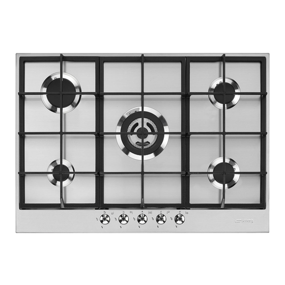
Page 8: Description
Description 2 Description 2.1 General Description 60 cm 70 cm central UR burner 70 cm lateral UR burner 1. Control panel 7. Ultra-rapid burner external crown (UR2 ext.) 2. Auxiliary burner (AUX) 8. Ultra-rapid burner internal crown (UR2 3. Semi-rapid burner (SR) int.) 4. -
Page 9: Symbols
Description 2.2 Symbols Burner knobs Cooking zones Front left Centre left Rear left Central For lighting and adjusting the hob burners. Rear right Press and turn the knobs anti-clockwise to Central right in order to light the relative burners. Turn the Front right knobs to the zone between the maximum and minimum... -
Page 10: Use
3 Use Improper use 3.1 Instructions Risk of damage to surfaces Improper use Danger of burns • Do not use aluminium foil to cover the burners or hob body. • Make sure that the flame-spreader • Cooking vessels or griddle plates crowns are correctly positioned in their should be placed inside the perimeter of housings with their respective burner... -
Page 11: Using The Hob
3.3 Using the hob Correct positioning of the flame- spreader crowns and burner caps All the appliance’s control and monitoring devices are located together on the front Before lighting the hob burners, make sure panel. The burner controlled by each knob that the flame-spreader crowns are is shown next to the knob. - Page 12 Correct positioning of the pan supports Also refer to the marking “FRONT” stamped under the front of each pan To install the pan supports, follow the support as an additional aid to positioning instructions as shown in the following them correctly on the hob. figures.
- Page 13 Practical tips for using the hob Using a griddle For better burner efficiency and to minimise gas consumption, use pans with lids and of suitable size for the burner, so that the flames do not reach up the sides of the pan. Once the contents come to the boil, turn down the flame far enough to ensure that the liquid does not boil over.
-
Page 14: Cleaning And Maintenance
Cleaning and maintenance 4 Cleaning and maintenance 4.2 Cleaning the appliance To keep the surfaces in good condition, 4.1 Instructions they should be cleaned regularly after use. Let them cool first. Improper use Risk of damage to surfaces Ordinary daily cleaning Always and only use specific products that •... - Page 15 Cleaning and maintenance Hob pan support grids Flame-spreader crowns and burner caps Remove the pan support grids and clean For easier cleaning, the flame-spreader them in lukewarm water and non-abrasive crowns and the burner caps can be detergent. Make sure to remove any removed.
-
Page 16: Installation
Installation 5.2 Section cut from the countertop 5 Installation The following operation requires 5.1 Safety instructions building and/or carpentry work and must therefore be carried out Heat production during appliance by a competent tradesman. operation Installation can be carried out on Risk of fire various materials such as masonry, metal, solid wood or plastic... - Page 17 Installation Dimensions: Location of gas and 70 cm models: electrical connections (measurements in 60 cm models: View from underneath G Gas connection E Electrical connection View from underneath G Gas connection E Electrical connection View from the back View from the back View from the right View from the right...
-
Page 18: Mounting
Installation 5.3 Mounting On top of an empty kitchen unit or drawers Over built-in oven unit If there are other pieces of furniture (lateral The clearance between the hob and the walls, drawers, etc.), dishwashers or fridges kitchen furniture or other installed under the hob, a double-layer wooden appliances must be enough to ensure base must be installed at least 10 mm from... -
Page 19: Fixing Using Brackets
Installation Hob seal 5.4 Fixing using brackets The figures below indicate the exact To prevent leakage of liquid between the position of the holes to be used to attach the frame of the hob and the work surface, put hob to the work surface correctly. the insulating seal provided in position before assembly. -
Page 20: Gas Connection
Installation Screw the fixing brackets (A) into the holes General information on the sides of the bottom casing to Connection to the gas mains can be made properly fasten the hob to the structure. using a rigid copper pipe or a continuous wall steel hose in compliance with the provisions established by the applicable standard. - Page 21 Installation Connection with a steel hose with conical Connection to LPG fitting Use a pressure regulator and make the Make the connection to the gas mains connection on the gas cylinder following using a continuous wall steel hose whose the guidelines set out in the standards in specifications comply with the applicable force.
- Page 22 Installation Extraction of the combustion products 1 Extraction using a hood 2 Extraction without a hood The combustion products may be extracted by means of hoods connected to a natural draught chimney whose efficiency is certain A Single natural draught chimney or via forced extraction.
-
Page 23: Adaptation To Different Types Of Gas
Installation 5.6 Adaptation to different types of 3. Pull the knobs upwards to remove them. If other types of gas are to be used, the nozzles must be replaced and the primary air must be adjusted. The hob has to be removed in order to replace the nozzles and adjust the burners. - Page 24 Installation Replacing nozzles Adjusting the minimum setting for natural or town gas 1. Light the burner and turn it to the minimum position. 2. Extract the gas cock knob and turn the adjustment screw next to the gas cock spindle (depending on the model) until the correct minimum flame is achieved.
- Page 25 Installation Adjusting the minimum setting for LPG • Tighten the screw located at the side of the cock spindle clockwise all the way. Following adjustment to a gas other than the one originally set in the factory, replace the gas setting label on the appliance with the one corresponding to the new gas.
- Page 26 Installation Gas types and Countries Gas types IT GB-IE FR-BE DE RU DK 1 Natural Gas G20 20 mbar • • • • • • • • • G20/25 20/25 mbar • 2 Natural Gas G20 • 25 mbar 3 Natural Gas G25 25 mbar •...
- Page 27 Installation Burner and nozzle characteristics tables 60 cm models: 1 Natural Gas G20 – 20 mbar Rated heating capacity (kW) 1.10 Nozzle diameter (1/100 mm) Reduced flow rate (W) 1600 Primary air (mm) 2 Natural Gas G20 – 25 mbar Rated heating capacity (kW) Nozzle diameter (1/100 mm) Reduced flow rate (W)
- Page 28 Installation 8 Natural gas G2.350 – 13 mbar Rated heating capacity (kW) Nozzle diameter (1/100 mm) Reduced flow rate (W) Primary air (mm) 9 LPG G30/31 - 30/37 mbar Rated heating capacity (kW) Nozzle diameter (1/100 mm) Reduced flow rate (W) 1600 Primary air (mm) Rated flow rate G30 (g/h)
- Page 29 Installation 70 cm models: 1 Natural Gas G20 – 20 mbar UR2 int. UR2 ext. Rated heating capacity (kW) 1.10 Nozzle diameter (1/100 mm) Reduced flow rate (W) 1600 1400 Primary air (mm) 2 Natural Gas G20 – 25 mbar UR2 int.
- Page 30 Installation 8 Natural gas G2.350 – 13 mbar UR2 int. UR2 ext. Rated heating capacity (kW) Nozzle diameter (1/100 mm) Reduced flow rate (W) Primary air (mm) 9 LPG G30/31 - 30/37 mbar UR2 int. UR2 ext. Rated heating capacity (kW) 1.10 Nozzle diameter (1/100 mm) Reduced flow rate (W)
-
Page 31: Electrical Connection
Installation 5.7 Electrical connection General information Check the grid characteristics against the Power voltage data indicated on the plate. Danger of electrocution The identification plate bearing the technical data, serial number and brand • Have the electrical connection name is visibly positioned on the appliance. performed by authorised technical Do not remove this plate for any reason. -
Page 32: Instructions For The Installer
Installation 5.8 Instructions for the installer Connection with plug and socket • The plug must be accessible after Make sure that the plug and socket are of installation. Do not bend or trap the the same type. power cable. Avoid using adapters and shunts as these •...
Need help?
Do you have a question about the PX375 and is the answer not in the manual?
Questions and answers