
Related Manuals for Greenlee 967


Summary of Contents for Greenlee 967
- Page 1 INSTRUCTION MANUAL 00967 Deluxe Force Gauge Read and understand all of the instructions and safety information in this manual before operating or servicing this tool. 999 2021.2 © 2002 Greenlee Textron IM 1255 REV 3 1/02...
-
Page 2: Table Of Contents
Replacement manuals are available upon request at no charge. All specifications are nominal and may change as design improve- ments occur. Greenlee Textron shall not be liable for damages resulting from misapplication or misuse of its products. KEEP THIS MANUAL... -
Page 3: Important Safety Information
Failure to follow instruc- tions and safety information can result in severe injury or death. Greenlee Textron / Subsidiary of Textron Inc. Electric shock hazard. • Do not expose tool to rain or use in wet or damp locations. -
Page 4: Principle Of Operation
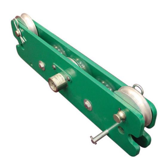
Weight ... 13.6 kg (30 lb) Maximum Rope Size ... 22 mm (7/8") Greenlee Textron / Subsidiary of Textron Inc. The tension on the rope is measured at the center roller. That roller presses against a load cell that sends an electronic signal to the digital display unit. -
Page 5: Setup / Installation
5. Align the holes and insert the hitch pin. Greenlee Textron / Subsidiary of Textron Inc. Mounting to the Ultra Tugger™ 1. See the manual supplied with the Ultra Tugger™. - Page 6 5. Replace the outer rollers. 6. Replace the hitch pins. 7. Replace the hitch pin clips. Greenlee Textron / Subsidiary of Textron Inc. Electrical Connection 1. Plug the patch cable into the load pin. 2. Twist the front of the connector clockwise to lock it in place.
-
Page 7: Operation
MENU: Press to enter the configuration/calibration mode. RESET: Press to reset the peak or tare readings. Greenlee Textron / Subsidiary of Textron Inc. With no load on the rope, the display should read “0” ( 4.5 kg or 10 lbs). Slight variations as the unit sits idle are normal. -
Page 8: Configuration
Strain Gage Meter operator’s manual supplied. To display kilograms instead of pounds change the value for: In the event any of the default values set by the factory are changed by accident, the Greenlee default values are listed below. Menu Topic INPT (signal input) DEC.P (decimal point) -
Page 9: Exploded View / Parts List - Roller Assembly
Screw, cap, 3/8-16 x .625 button head ... 2 905 4875.2 Inner race, Torrington #1620 ... 1 905 4841.8 Bearing, NL #1620-9 ... 2 Greenlee Textron / Subsidiary of Textron Inc. Part No. 905 4845.0 905 4846.9 905 4876.0 905 4840.0 Attachments Part No. -
Page 10: Digital Display
00967 Deluxe Force Gauge Digital Display Greenlee Textron / Subsidiary of Textron Inc. 4455 Boeing Dr. • Rockford, IL 61109-2988 USA • 815/397-7070... - Page 11 Power cord ... 1 918 6325.2 Receptacle, 115 Vac ... 1 918 6326.0 Strain relief ... 1 918 6319.8 Switch (with mounting nuts) ... 2 Greenlee Textron / Subsidiary of Textron Inc. GREEN WHITE BLACK 17,19 Part No. 500 0961.3 500 0962.1...
-
Page 12: Wiring Connections For Strain Gage Monitor
Monitor Wire Unit Neutral Wire Unit Ground Wire Unit Greenlee Textron / Subsidiary of Textron Inc. 4455 Boeing Drive, Rockford, IL 61109-2988 USA Customer Service (International): 815/397-7070 • Fax: 815/397-9247 Customer Service (North America): 800/435-0786 • USA Fax: 800/451-2632, 815/397-1865...
Need help?
Do you have a question about the 967 and is the answer not in the manual?
Questions and answers